
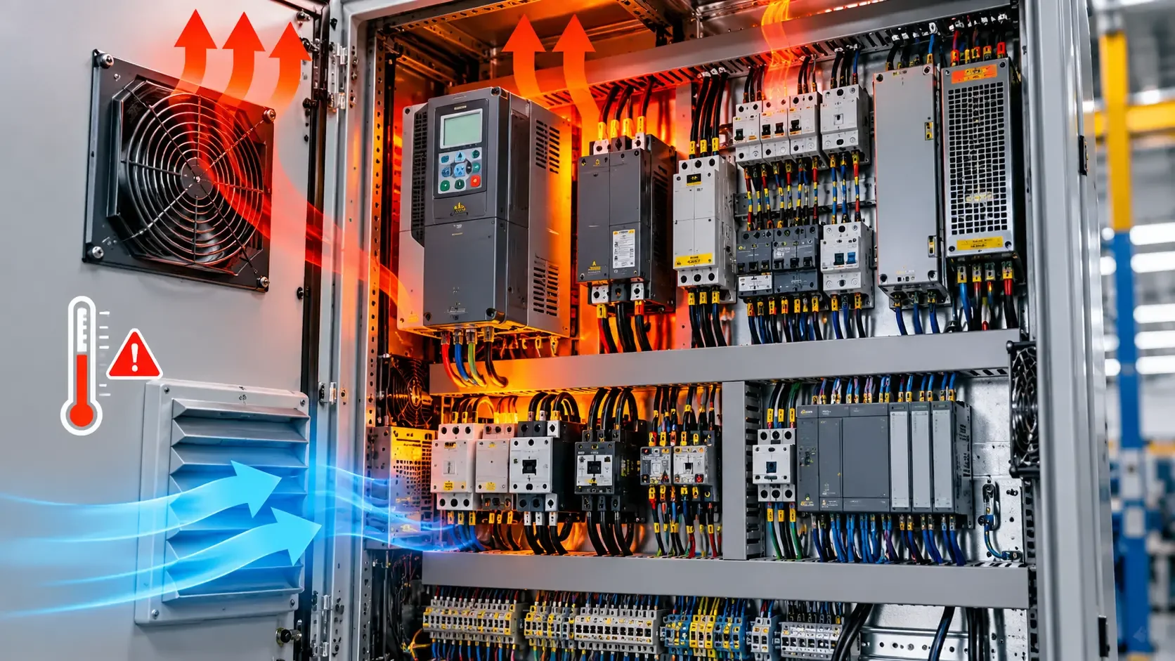
Overheating is a heat-balance problem
Every energized component dissipates some power as heat. The internal cabinet temperature stabilizes only when the enclosure can transfer that heat to its surroundings at the same rate it is produced. Overheating occurs when internal losses increase, heat transfer decreases, the ambient temperature rises, or the original thermal design no longer matches the installed equipment and duty cycle.
The first task is to define the symptom accurately. A single hot terminal is a different failure from a uniformly hot enclosure. A cabinet that overheats only on warm afternoons suggests a different path from one that heats rapidly when a particular motor starts. Record the location, time, machine load, ambient condition, fan or cooler state and any recent changes.
Common heat sources and their signatures
| Pattern | Typical evidence | Diagnostic direction |
|---|---|---|
| One terminal, pole or conductor is much hotter than comparable phases | Local discoloration, insulation damage, abnormal voltage drop or unequal temperature | Loose or contaminated connection, damaged conductor, incorrect termination or overloaded pole |
| One power component is hot under normal cabinet temperature | High measured load, blocked local airflow or device alarm history | Component loading, switching loss, derating, internal wear or incorrect application |
| Upper part of the enclosure is uniformly hot | Strong vertical temperature gradient and congested layout | Natural convection is blocked or heat-producing devices are poorly arranged |
| Entire enclosure rises with room temperature | Similar internal-to-ambient difference but higher absolute temperatures | Ambient condition exceeds the original design assumption |
| Temperature rises after filters become dirty | Reduced airflow and fan noise or speed change | Maintenance failure, clogged filter, failed fan or obstructed air path |
| Hot weather coincides with moisture or corrosion | Cooler runs continuously and surfaces approach condensation conditions | Cooling control, sealing or condensation-management problem |
Excessive electrical loading
Power supplies, drives, transformers, contactors, braking components and protective devices all create losses. Their heat output depends on load, switching behavior, efficiency and mounting conditions. A cabinet may have been adequate when commissioned but become overloaded after additional drives, power supplies or network equipment were installed.
Measure actual operating currents and compare them with the equipment design, manufacturer instructions and expected duty cycle. Look for continuous loads that were assumed to be intermittent, repeated acceleration or braking, frequent contactor operation, and simultaneous operation of loads that were originally sequenced.
Three-phase current imbalance can concentrate heating in one pole or conductor. Nonlinear loads can also change current and heating patterns in conductors and transformers. The correct response is measurement and comparison, not an assumption based only on the total nameplate power.
High-resistance connections
A loose, contaminated or damaged connection produces localized heat because electrical resistance increases at the joint. Common locations include breaker terminals, contactor poles, fuse holders, distribution blocks, neutral connections, power-supply terminals and field-cable entries.
Thermal imaging is useful for finding relative differences between comparable phases or identical devices under similar load. It is not a substitute for electrical testing. Apparent temperature depends on surface emissivity, reflection, viewing angle, focus and access. Shiny metal can reflect surrounding heat and give a misleading reading. Correlate the image with load current, voltage drop, physical inspection and the equipment's condition.
After safe isolation, inspect for discoloration, softened insulation, damaged strands, incorrect ferrules or lugs, conductor movement and terminal damage. Tightening must follow the component manufacturer's procedure; blindly applying more torque can damage a terminal and worsen the connection.
Failed or restricted cooling
Forced-ventilation systems depend on a complete airflow path. A running fan does not prove adequate cooling. Filters can be clogged, fan blades can be contaminated, airflow can be reversed, internal wiring can obstruct the path, or inlet and outlet openings can recirculate the same warm air.
Verify the fan direction and actual airflow. Check that cool air reaches the heat-producing equipment and that hot air can leave without short-circuiting back to the inlet. Inspect thermostats, fan relays, protective devices and alarm contacts. For air conditioners or heat exchangers, review operating status, condensate handling, clean heat-transfer surfaces and enclosure sealing according to the manufacturer's maintenance instructions.
Leaving the door open is not a repair. It can defeat the enclosure's protection against dust, conductive contamination, moisture and accidental contact, while also changing the designed airflow.
Layout and enclosure problems
Heat-producing devices require the clearances and orientation specified by their manufacturers. Closely packed drives, power supplies or contactors can heat one another. Components mounted above large heat sources may receive air that is already warm. Dense wire ducts can block natural convection and make measurement or maintenance difficult.
The enclosure itself must suit the heat load and environment. A sealed cabinet prevents contaminated air from entering but also restricts direct ventilation. A filtered fan can move heat efficiently only when the surrounding air is sufficiently clean and cool. A heat exchanger or closed-loop cooler may be necessary in a hot, dusty or wet environment, but it must be sized and maintained for the actual conditions.
Solar gain, nearby ovens, hot process piping and poor room ventilation can raise the external temperature beyond the original assumption. Measure ambient temperature at the cabinet location over the real production cycle rather than relying on a distant room sensor.
A structured diagnostic survey
- Define the operating condition. Record production state, loads, ambient temperature, enclosure temperature, alarms and the time required for the symptom to appear.
- Inspect externally. Check blocked vents, dirty filters, failed fans, direct heat sources, sunlight, damaged seals and obstructions around the enclosure.
- Review recent changes. Identify added components, altered drive parameters, increased machine speed, changed duty cycle or wiring modifications.
- Map temperatures safely. Compare similar phases and devices under comparable load. Note both localized hot spots and overall air-temperature patterns.
- Measure electrical loading. Check relevant currents, phase balance and voltage drop at suspected connections using appropriate instruments and procedures.
- Verify the cooling path. Confirm fan control, airflow direction, filter condition, internal clearance and cooler or heat-exchanger operation.
- Inspect de-energized connections. Follow the approved isolation procedure before examining terminals, conductors and mounting condition.
- Correct the root cause and trend the result. Repeat measurements under the same load and ambient conditions. A lower temperature immediately after a repair is useful evidence, but stable performance over the normal operating cycle is the real verification.
Common diagnostic mistakes
- Comparing temperatures of phases that are carrying different currents.
- Treating the brightest point in a thermal image as an exact temperature without considering surface properties.
- Replacing a fan without cleaning the filter or proving the airflow path.
- Adding more ventilation without considering dust, moisture or enclosure protection.
- Tightening every terminal indiscriminately instead of inspecting and following approved torque procedures.
- Ignoring added components and production changes made after the cabinet was designed.
- Measuring cabinet temperature without recording the ambient temperature and machine load.
Technical conclusion
Cabinet overheating is rarely solved well by one temperature reading. Determine whether the problem is localized or general, correlate temperature with electrical load and machine state, and verify the complete heat-removal path. The lasting correction may be a repaired termination, restored airflow, revised layout, reduced loss, improved enclosure cooling or a combination of these measures. Verification must reproduce the operating condition that originally caused the problem.


