
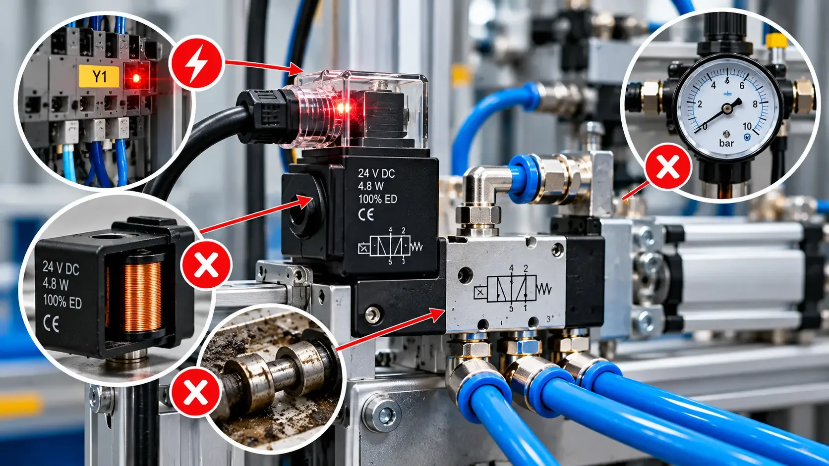
One symptom, four different systems
When a solenoid valve does not actuate, the visible symptom is often simple: the cylinder does not move, a gripper does not release or a pilot-operated valve remains in its previous state. The cause can be in the control command, electrical power path, solenoid and mechanical operator, or pneumatic circuit.
The fastest diagnosis follows the energy path in order. Confirm that a command exists, prove that usable voltage reaches the coil under load, determine whether the coil creates a magnetic action, verify that the valve spool or poppet shifts, and then check whether pressure and flow can reach the actuator.
Read the valve function before testing
Identify the valve type and its normal state from the symbol and part information. A single-solenoid spring-return valve behaves differently from a double-solenoid bistable valve. A pilot-operated valve may require a minimum pressure differential or a separate pilot supply. A valve with a manual override can help separate an electrical problem from a pneumatic or mechanical one, but the override must be used only when unexpected machine movement is controlled.
Also establish what “failed to actuate” means. No audible click, a click without flow, partial movement, delayed movement and intermittent operation point in different directions.
| Observation | What it proves | What it does not prove |
|---|---|---|
| PLC output indicator is on | The control logic is requesting the output at that module | That voltage reaches the coil or that the output can supply current |
| Connector LED is on | Voltage exists at some point in the connector circuit | Correct voltage at the coil under load or a healthy neutral/return path |
| Solenoid clicks | The armature is probably moving | That the main valve stage has shifted or that air can flow |
| Manual override moves the actuator | The downstream pneumatic path can operate under that condition | That the electrical command, coil or normal pilot path is healthy |
| Coil is warm | Current has flowed or heat has transferred from the valve | That the magnetic force is sufficient or the voltage is correct |
Electrical diagnostic path
- Confirm the intended command. Check the machine state, interlocks, safety outputs and sequence conditions. Use the PLC program and I/O diagnostics to distinguish “the logic did not command it” from “the command was present but the field device did not respond.”
- Measure at the valve during the command. Measure across the two coil terminals, not from one terminal to an assumed reference. A high-impedance meter can display a misleading voltage on an open conductor or through leakage from an electronic output. The important reading is the voltage across the energized coil while it is connected.
- Check the return path and switching device. Inspect the PLC output, fuse, interposing relay, connector, cable and common/return conductor. A contact with high resistance may show normal voltage without load and collapse when the coil is energized.
- Verify the coil rating and supply type. Confirm that the coil is intended for the applied AC or DC supply. Some connectors contain indicators, rectifiers or suppression components. Polarity can matter when a DC coil or connector includes a diode.
- Test the de-energized coil. After isolation, compare coil resistance and insulation condition with manufacturer information or a known identical device. An open winding indicates a break; an unusually low resistance can indicate shorted turns, but resistance alone does not prove that the mechanical armature moves correctly.
- Inspect suppression and output compatibility. A failed suppression diode or varistor can short the circuit or repeatedly operate protection. Conversely, an unsuitable suppression method can slow coil release and affect machine timing.
Do not force voltage directly onto a coil unless the test method is authorized, the correct supply is known, the PLC output is isolated from backfeed and all resulting machine movement is controlled.
Mechanical valve faults
A healthy coil can produce magnetic force while the armature, pilot poppet or main spool remains stuck. Contamination, corrosion, varnish-like deposits, damaged seals, misalignment and mechanical wear can all prevent full travel. A coil that is not fully seated on its operator may overheat or produce insufficient force.
If the valve has a manual override, compare manual and electrical operation under the same safe pneumatic conditions. If manual operation works but electrical operation does not, focus on the command, coil, connector and armature. If neither works, investigate the valve mechanism, pressure conditions and downstream circuit.
Intermittent sticking often appears after a long idle period, at a particular temperature or after contamination enters the air system. Record those conditions. Replacing a valve without correcting water, oil, particles or unsuitable lubrication can make the same failure return.
Pneumatic causes that imitate an electrical failure
The valve can shift correctly while the actuator remains stationary. Check the supply pressure at the valve during demand, not only at the compressor or main regulator. A closed isolation valve, clogged filter, undersized line, frozen or restricted exhaust, silencer blockage, kinked tube or large simultaneous air demand can remove the pressure differential needed for operation.
Pilot-operated valves deserve special attention. The pilot source must be present and correctly connected. If the main ports are reversed or exhaust ports are obstructed, the pilot stage may click without shifting the main spool. For an externally piloted valve, loss of pilot pressure can stop operation even when main supply pressure appears normal.
At the actuator, inspect flow controls, end-position cushioning and mechanical load. A nearly closed flow control or blocked exhaust can make movement so slow that it looks like no actuation. A cylinder at a hard stop with a side load may require more force than the available pressure can produce.
A repeatable troubleshooting procedure
- Record the valve identifier, symptom, machine state and whether the fault is constant or intermittent.
- Confirm the valve symbol, coil rating, normal state, pilot arrangement and port connections.
- Observe the PLC output and measure voltage across the connected coil during the failed command.
- Listen and feel for armature action without placing hands near moving machinery.
- Use the manual override only under an approved safe condition and compare the response.
- Measure supply and pilot pressure at the valve while the circuit is asked to operate.
- Check exhaust flow, silencers, tubing, flow controls and the actuator's mechanical freedom.
- Correct the identified fault, restore all connectors and guards, then verify several complete cycles under normal load.
Common diagnostic mistakes
- Treating a lit PLC output LED as proof that the coil is energized.
- Measuring from the switched wire to protective earth instead of across the coil.
- Replacing the coil without checking whether the valve armature is stuck.
- Ignoring polarity in a connector that contains a suppression diode.
- Operating a manual override without controlling the cylinder or stored energy.
- Checking pressure only at the main regulator rather than at the valve during flow.
- Installing a replacement with the wrong valve function, pilot arrangement or coil rating.
Technical conclusion
A solenoid valve is an interface between logic, electricity, magnetism, mechanics and compressed air. Diagnose it in that order. Prove the command, measure the loaded electrical circuit, confirm mechanical shifting and then verify pressure and flow. This prevents a pneumatic restriction from being mistaken for a PLC fault—and prevents an open return conductor from being mistaken for a failed valve.


