
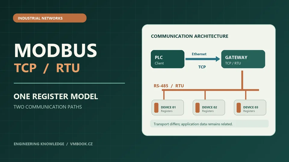
A PLC can read an energy meter over Ethernet, communicate with a temperature controller through an RS-485 converter and collect data from a drive through an industrial protocol gateway. All three devices may be described as using Modbus, yet their connection settings and failure modes are different.
The confusion often begins when a device is reachable but its registers return the wrong values, or when a Modbus TCP gateway responds to the network while a serial instrument behind it remains unavailable.
Modbus is comparatively simple at the application layer. The engineering challenge is usually understanding how that application protocol is transported, how its data addresses are represented and which part of the communication chain has failed.
This guide compares Modbus TCP and Modbus RTU and provides a structured method for interpreting the most common industrial communication symptoms.
1. One Modbus application protocol, two common transports
At the application level, Modbus uses a client–server request/response model. A client requests data or an action; a server interprets the function code and returns a response or an exception.
In older literature the terms master and slave appear frequently. Current descriptions commonly use client and server. Both terminology sets may appear in device manuals, but the application idea is the same.
The request describes the operation using a function code, an address or other parameters, and any required data.
The transport supplies the surrounding communication mechanism.
| Property | Modbus TCP | Modbus RTU |
|---|---|---|
| Common physical network | Ethernet through TCP/IP | Serial link, commonly RS-485 |
| Application model | Client request, server response | Client request, server response |
| Common destination | Server IP address and TCP port, normally 502 | Serial station address on the bus |
| Message framing | MBAP header followed by Modbus PDU | Station address, Modbus PDU and CRC |
| Error detection associated with framing | Network-layer and TCP checks; no RTU CRC in the Modbus TCP ADU | CRC-16 at the end of the RTU frame |
| Message boundary | Length field in the MBAP header | Serial timing rules and RTU frame structure |
| Shared medium concerns | Ethernet switching, addressing, TCP connection state and device load | Baud rate, serial settings, line topology, termination and timing |
| Typical equipment | Ethernet PLCs, HMIs, meters and gateways | Legacy drives, meters, temperature controllers and distributed devices |
Both transports can represent the same types of coils and registers. They do not, however, use the same packet framing.
2. Modbus function codes describe the requested operation
A Modbus function code identifies the action requested by the client. A device supports only the functions implemented for that particular product and configuration.
The functions used most often in maintenance work include:
| Function code | Name | Data category |
|---|---|---|
| 01 | Read Coils | Discrete read/write bits |
| 02 | Read Discrete Inputs | Discrete read-only bits |
| 03 | Read Holding Registers | Sixteen-bit holding-register values |
| 04 | Read Input Registers | Sixteen-bit read-only input-register values |
| 05 | Write Single Coil | One writable coil |
| 06 | Write Single Register | One writable holding register |
| 15 | Write Multiple Coils | A group of coils |
| 16 | Write Multiple Registers | A group of holding registers |
Function availability is device-specific. The existence of holding registers does not mean that a device supports every write function. In real maintenance work, read-only information should be preferred for initial evidence collection, and write operations must be treated as controlled engineering changes.
Engineering principle: A readable value does not prove that all register functions are available. The configured function code must match both the data category and the device's implementation.
3. Four data areas are often confused
Modbus distinguishes four traditional types of addressable data.
- Coils: Single-bit values generally accessed with coil functions.
- Discrete inputs: Single-bit read-only values.
- Input registers: Sixteen-bit read-only register values.
- Holding registers: Sixteen-bit register values, often used for parameters, measured values or control data.
A manufacturer may publish these areas using familiar reference prefixes such as 0xxxx, 1xxxx, 3xxxx and 4xxxx. Those prefixes are a documentation convention, not literal bytes transmitted as part of a Modbus address.
For example, a documented holding register called 40001 usually indicates the first item in a one-based holding-register list. The zero-based protocol address in the request is often 0.
That mapping must always be checked against the manufacturer's address convention and the configuration of the client software.
4. The 40001 problem: reference number versus protocol offset
One of the most common Modbus integration errors is an off-by-one register address.
A device manual says: "Temperature value — Holding Register 40001." One engineering program asks for register 40001. Another asks for offset 0. A third asks for register 1 after the function type has been selected.
Depending on the software, those inputs may describe the same location or entirely different ones.
| Manual notation | Possible protocol interpretation | Important caution |
|---|---|---|
| 40001, holding-register convention | Function 03, address 0 | Check whether the software automatically removes the 40000 reference base |
| 40002, holding-register convention | Function 03, address 1 | Some engineering tools expect one-based input instead |
| 30001, input-register convention | Function 04, address 0 | The data category and function code must agree |
| Hex address 0x0010 | Decimal protocol address 16 | Do not confuse hexadecimal notation with a 4xxxx register reference |
This is a notation problem, not necessarily a communication failure.
When a device answers successfully but the value appears unrelated to the expected measurement, the correct first question may be whether the client and the manual use the same addressing convention.
Diagnostic principle: Record the function code, transmitted protocol address and documentation reference separately. A display labeled simply "register" can conceal the distinction.
5. Sixteen-bit registers do not automatically define a 32-bit engineering value
A standard Modbus register contains 16 bits. A device may store a 32-bit integer or IEEE 754 floating-point value across two adjacent registers.
The Modbus specification defines how individual 16-bit register values are represented, but it does not establish a universal word order for every vendor's two-register floating-point format.
As a result, the same two registers may produce a realistic measurement in one interpretation and an implausible number in another.
| Interpretation issue | Possible symptom | What the device manual must clarify |
|---|---|---|
| Signed versus unsigned 16-bit value | A normal negative value appears as a large positive number | Signed encoding and measurement range |
| Scale factor | A temperature of 23.5 appears as 235 | Resolution or scaling multiplier |
| Two-register word order | A 32-bit number is incorrect despite valid communication | High-word/low-word ordering |
| IEEE 754 interpretation | Floating-point value is nonsensical | Data type and register order |
| Wrong register area | A different value or exception is returned | Correct function code and address table |
A valid response can therefore contain invalidly interpreted engineering information. Communication and data interpretation must be evaluated separately.
6. The Modbus TCP message begins with an MBAP header
Modbus TCP carries a Modbus Protocol Data Unit (PDU) inside a TCP-oriented Application Data Unit (ADU).
A standard Modbus TCP ADU begins with a seven-byte MBAP header, followed by the function code and its data.
| MBAP field | Length | Purpose |
|---|---|---|
| Transaction Identifier | 2 bytes | Associates a request with its response |
| Protocol Identifier | 2 bytes | Identifies the protocol; zero for Modbus |
| Length | 2 bytes | Counts following bytes, including the Unit Identifier and PDU |
| Unit Identifier | 1 byte | Identifies the intended unit, especially relevant to gateways |
The commonly registered TCP port for Modbus is 502.
Unlike an RTU serial frame, a normal Modbus TCP ADU does not append the RTU CRC-16. The network transport has its own integrity checks, while the MBAP length and transaction fields provide the framing and matching information required by the Modbus TCP implementation.
A device accepting a TCP connection on port 502 is not automatically proof that it supports the expected function or register.
7. What the Modbus TCP Unit Identifier really means
An IP address identifies the reachable TCP endpoint. The Unit Identifier inside the MBAP header has a different role.
When a Modbus TCP-to-RTU gateway serves several serial devices behind one Ethernet address, the Unit Identifier is commonly used to indicate which downstream serial station should receive the request.
For a Modbus TCP device that is the final destination, the supported Unit Identifier may be fixed, ignored or vendor-defined. It should not be guessed from unrelated equipment.
An example network might have:
- A PLC acting as a Modbus TCP client.
- One Ethernet-connected Modbus gateway.
- Three serial devices with distinct station addresses behind that gateway.
All three devices can share the gateway's IP endpoint, while their downstream identity is distinguished through the gateway's configured routing behavior.
Common mistake: Assuming that the Unit Identifier is always irrelevant, or that it is always the same thing as an IP address. Its significance depends on the architecture.
8. Modbus RTU uses serial framing and CRC-16
A Modbus RTU message contains the serial station address, the Modbus function and data, followed by a 16-bit CRC.
On common RS-485 multidrop installations, several devices share a communication pair. Each configured server must have an appropriate station address for the intended arrangement.
The serial connection also depends on compatible communication settings such as baud rate, parity, stop bits and RTU framing behavior.
The RTU message boundary uses timing rules described by the Modbus Serial Line Protocol and Implementation Guide. A sufficiently long silent interval between frames separates messages; in typical RTU rules this corresponds to at least 3.5 character times. Character timing and implementation details must be interpreted through the applicable specification and equipment documentation.
The serial CRC checks the RTU frame integrity. A CRC error is different from a valid Modbus exception response.
9. Why RS-485 wiring is not just a connector choice
RS-485 describes an electrical signaling interface. Modbus RTU is one communication protocol that can use it.
A typical two-wire RS-485 multidrop network has differential communication conductors and a design that accounts for signal reference, cable construction, segment layout and electrical termination as required by the equipment manufacturers.
Problems may occur when the installed physical network departs from the intended topology or when connected devices have unsuitable interface settings.
Potential diagnostic factors include:
- Incorrect or conflicting station addresses.
- Serial communication parameters that do not match.
- Unsuitable line termination or reference design.
- Intermittent connectors or damaged wiring.
- Excessive cable length or unsuitable branch layout for the deployed system.
- Electromagnetic interference or loss of device power.
These factors require a machine-specific assessment. Physical work on an operating industrial installation is for authorized personnel following the site's safety rules.
Engineering principle: RS-485 electrical compatibility, RTU frame integrity and valid Modbus application responses are three separate things.
10. A Modbus TCP gateway can be healthy while the RTU device is missing
A common fault is a gateway that responds to Ethernet diagnostics but reports that it cannot reach the intended serial device.
This does not automatically mean the gateway has failed. It may have a working Ethernet interface and TCP server while the downstream serial path is unavailable or the target unit is not responding.
| Observation | More useful diagnostic direction |
|---|---|
| Gateway accepts the TCP connection, but downstream request times out | Serial device availability, gateway routing and serial communication conditions |
| Gateway returns an exception relating to a downstream target | Interpret the specific Modbus exception and gateway documentation |
| One serial station responds, another does not | Station-specific identity, device condition or relevant communication path |
| All serial stations disappear at the same moment | Shared serial segment, gateway serial interface or common power conditions |
| Values are returned but appear shifted | Register address convention, scaling or multi-register data interpretation |
The gateway can also have different configuration modes. A protocol-converting gateway that expects Modbus TCP framing is not interchangeable with a transparent TCP serial server that merely forwards RTU bytes.
Do not confuse Modbus TCP with RTU frames transported transparently through a TCP socket. Both can use Ethernet infrastructure, but the application framing expected by the endpoint is different.
11. Exception responses contain useful information
Modbus provides standardized exception responses when a server receives a request but cannot perform the requested function normally.
An exception response uses the original function code with its most significant bit set, followed by an exception code.
For example, an exception for function 03 uses exception function code 0x83.
| Exception code | Name | Meaning in diagnosis |
|---|---|---|
| 01 | Illegal Function | The function is not allowed or supported in the relevant context |
| 02 | Illegal Data Address | The requested address or range is not accepted |
| 03 | Illegal Data Value | A request value or structure is not accepted |
| 04 | Server Device Failure | The server encountered a failure while attempting the action |
| 0A | Gateway Path Unavailable | The gateway cannot use the required communication path |
| 0B | Gateway Target Device Failed to Respond | The target behind the gateway did not respond as required |
Not all devices implement every exception in the same way. The exact product documentation and observed response remain authoritative.
An exception response is fundamentally different from no response at all. It shows that some part of the request reached a device capable of returning a defined Modbus error.
12. Timeout, exception and wrong value are three different failures
These common symptoms should be handled as separate diagnostic categories.
Timeout: The expected response did not arrive within the client's configured timeout. Possible reasons include a missing device, communication disruption, an unsuitable serial configuration, an unavailable gateway path or simply a longer-than-expected response time.
Modbus exception: A responding device reported that the requested operation could not be completed. The exception code narrows the explanation.
Wrong-looking value: The response was successfully received, but the data may have been interpreted using the wrong address base, function code, scaling or data type.
| Symptom | What has been demonstrated | What remains unproven |
|---|---|---|
| No response | No valid response was received within the test's conditions | Whether the server, transport or gateway path was responsible |
| Exception 02 | A Modbus responder rejected the requested address/range | Whether the register documentation or client mapping is wrong |
| Valid response, implausible temperature | Communication returned data | Whether register mapping, scaling and data format agree |
| TCP connection established, RTU target missing | Ethernet-facing gateway service is reachable | Whether the serial station is operating correctly |
Replacing hardware before making these distinctions often prolongs the investigation.
13. Polling intervals and serial bus capacity matter
A Modbus client may request measurements continuously. In serial RTU networks, each request and response consumes time on the shared serial link.
The time required depends on the baud rate, frame length, required silent intervals and the device's response behavior. Gateway processing and timeouts add further delay.
For a rough illustration, ten devices each read once per second require at least ten request/response exchanges every second. Whether a particular serial bus can support that pattern depends on the actual frame sizes, configured communication speed and device response times.
Shorter client polling intervals do not magically make a slow device respond faster. Excessively frequent requests can contribute to timeouts and stale data, especially when many logical clients share one serial communication path through a gateway.
A useful baseline documents the intended refresh rate, device response characteristics and overall network loading.
14. Reconstructed factory case: the temperature value that was always wrong
Consider an illustrative factory control cabinet where a PLC reads temperature from a Modbus-capable measurement module.
The connection remains stable. The client receives successful responses. Yet the displayed temperature is consistently much higher than the physical process condition.
The first suspicion is a defective temperature sensor.
A review of the module documentation shows that the measurement is published as an integer with a scaling factor of ten. A raw value of 235 therefore represents 23.5 degrees in the device's configured engineering units rather than 235 degrees.
The network and device response were functioning. The problem was in the interpretation of the returned data.
Lesson: Successful communication and correct engineering meaning are separate requirements.
This is a reconstructed educational case, not a report of a specific factory incident.
15. Reconstructed factory case: a gateway that did not reach the meter
In a second illustrative case, a maintenance workstation can access a Modbus TCP gateway. Two meters behind its RS-485 interface are expected to provide register values.
Only one responds. The other generates a gateway target-timeout indication.
The team initially blames the Ethernet switch, because the error appears in the PLC's communication view. However, the successful TCP interaction with the gateway and the functioning first serial station narrow the fault domain.
The correct engineering investigation examines the documented identity, status and communication requirements of the unavailable downstream meter and the gateway's routing information.
Lesson: The point at which an alarm is displayed is not necessarily the point at which the failure originated.
16. A structured fault-finding method for Modbus installations
The following is a reasoning framework for authorized engineering review, not a procedure for changing live machine settings.
- Define the observed failure. Is the device unreachable, is a response missing, is an exception returned, or does a received value look incorrect?
- Identify the actual transport. Determine whether the documented path uses Modbus TCP, serial Modbus RTU, or a gateway/transparent serial arrangement.
- Record the communication identities. Separate TCP endpoint, Unit Identifier, serial station address, function code and register address.
- Preserve the evidence. Record the error classification, timestamp, controller state and available gateway or device diagnostics.
- Evaluate the relevant layer. Consider physical network condition, transport service, gateway routing, Modbus application response and value interpretation independently.
- Check the manufacturer's register mapping. Confirm address base, register category, function code, data type and scaling convention.
- Interpret any exception response. An exception is not equivalent to a timeout and should be reported with its exact code.
- Validate only through approved methods. Authorized commissioning and acceptance processes should establish whether the documented cause has been corrected.
A reliable conclusion explains why the original failure occurred, not merely why a temporary test began returning values.
17. Common Modbus troubleshooting mistakes
- "40001 always means I must transmit address 40001." Documentation references and zero-based protocol addresses are different concepts.
- "A green Ethernet LED proves the register should be readable." Network link status does not establish a valid Modbus request or response.
- "Modbus TCP frames end in the same CRC as RTU." Normal Modbus TCP uses MBAP framing, not the RTU CRC.
- "Every device has the same 32-bit word order." Multi-register data representation is vendor-specific.
- "The gateway IP address identifies every serial device behind it." Downstream identity often depends on the Unit Identifier and gateway mapping.
- "Exception 02 means the serial cable is broken." It indicates a rejected data address/range in a received Modbus exception response.
- "A TCP serial server and a Modbus protocol gateway are identical." Transparent serial forwarding and Modbus protocol conversion are different services.
- "Faster polling always improves data quality." Excessive request loading can degrade communication reliability.
- "Modbus automatically secures control commands." Conventional Modbus TCP and RTU lack modern authentication and encryption mechanisms in their original forms; protection depends on network architecture and supported security extensions.
18. Documentation that prevents repeated failures
A useful Modbus integration record should describe not only a device address, but the entire route from the client to the engineering value.
| Field | Example of useful documentation |
|---|---|
| Device role | Modbus TCP server, RTU server or gateway |
| Transport | Ethernet TCP/IP or serial RS-485 |
| Endpoint identity | IP endpoint, Unit Identifier and/or serial station address |
| Serial settings where relevant | Manufacturer-approved baud rate, parity and stop bits |
| Function code | 03 for a specified holding-register measurement |
| Register documentation | Manual reference and actual protocol offset |
| Data interpretation | Signedness, scale factor, data type and word order |
| Polling requirement | Expected measurement refresh and response characteristics |
| Relevant diagnostics | Device event history, gateway error and controller alarm |
| Change history | Replacement, configuration revision or software update |
When this information is available, a later maintenance team can distinguish a communication fault from a data-interpretation error much more quickly.
Technical conclusion
Modbus TCP and Modbus RTU share the same basic application data model but use different transport framing, addressing mechanisms and physical infrastructure.
Modbus TCP uses an MBAP header over TCP/IP. Modbus RTU uses serial station addressing, RTU framing and CRC checking, commonly on RS-485 networks. A gateway introduces another layer of identity and timing that must be documented.
The most useful troubleshooting habit is to separate transport availability, Modbus response status, register addressing and engineering-value interpretation. A device that does not respond, one that returns an exception and one that returns a correctly formatted but misunderstood number are not the same problem.
For related industrial network diagnostics, see Industrial Ethernet Diagnostics: What CRC Errors, Link Flaps and Packet Drops Really Mean and PROFINET vs PROFIBUS: Addressing, Configuration and Fault Diagnosis.
Official references
- Modbus Organization — Specifications and Implementation Guides, including the application protocol, serial-line and Modbus TCP documents.
- Modbus Application Protocol Specification V1.1b3, documenting data types, function codes and exception responses.
- Modbus Messaging on TCP/IP Implementation Guide V1.0b, describing MBAP, client/server implementation and gateways.
Cover illustration: original technical illustration prepared for vmbook.cz. It conceptually represents an Ethernet Modbus TCP client communicating through a gateway with multiple Modbus RTU devices on an RS-485 serial bus; it is not a manufacturer-specific installation drawing.

