
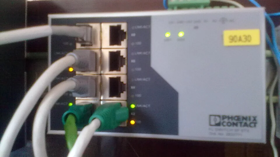
An EtherNet/IP device appears in the engineering workstation. Its network port reports an active Ethernet link. The device responds to an ordinary IP connectivity check, and its web interface may display a healthy status.
Yet the PLC reports that the remote I/O connection is faulted.
This situation is confusing only if basic Ethernet reachability is treated as equivalent to industrial I/O communication. It is not. EtherNet/IP uses ordinary Ethernet and IP infrastructure, but time-sensitive control data depends on an established Common Industrial Protocol (CIP) connection with compatible data, timing and device parameters.
A useful fault-finding method must distinguish the physical network, IP communication, device identification, CIP services and the cyclic I/O relationship that the control application requires.
1. What EtherNet/IP actually is
EtherNet/IP is an industrial networking technology that implements CIP over standard Ethernet and Internet Protocol technologies. It is maintained through ODVA specifications and is widely used with programmable controllers, remote I/O, motor drives, sensors and other automation equipment.
The name does not mean that an ordinary web or office Ethernet connection is automatically a valid industrial I/O connection. Ethernet is the underlying communication medium; CIP defines industrial application objects, services and relationships.
A typical installation may include a controller acting as the originator of a connection and one or more devices acting as targets. In everyday maintenance language, the terms scanner and adapter are also used, although exact capabilities depend on the device implementation.
The originator and target need to agree on the necessary communication parameters before the planned I/O exchange is established.
| Layer or function | What it establishes | What it does not prove |
|---|---|---|
| Ethernet physical link | An electrical or optical link exists between connected ports | The PLC has a healthy I/O connection |
| IP addressing and reachability | Appropriate IP communication can occur between interfaces | The device supports the expected CIP objects and connection |
| CIP identification and messaging | The device can participate in particular CIP services | The time-sensitive I/O connection is running |
| CIP I/O connection | The configured originator and target exchange the intended application data | Every sensor, actuator or process value is valid |
| Application and process logic | The controller interprets the received data in the machine sequence | The entire machine has no unrelated fault |
Key distinction: A reachable IP address is evidence of network communication, not proof that the controller's configured I/O relationship is established.
2. Explicit and implicit CIP messaging are different
EtherNet/IP supports two important forms of application communication.
Explicit messaging is commonly used for configuration, device information, diagnostics and request/response transactions. In ordinary EtherNet/IP implementations, it commonly uses TCP/IP.
Implicit messaging is commonly used for time-sensitive I/O data. It relies on a previously established connection and normally exchanges application data using UDP/IP at the configured production rate.
The descriptions explicit and implicit refer to how the application data and its meaning are represented within CIP communication, not to whether packets are visible on a network.
| Characteristic | Explicit CIP messaging | Implicit CIP I/O messaging |
|---|---|---|
| Typical use | Read information, configuration and diagnostics | Transfer recurring industrial process data |
| Common transport | TCP | UDP |
| Communication pattern | Request/response | Cyclic or other configured production trigger |
| Data interpretation | Service and object information carried with the request | Data format agreed during connection setup |
| Typical fault symptom | A diagnostic or information service is unavailable | Controller reports a faulted or timed-out I/O connection |
A device may answer explicit diagnostic requests while its implicit I/O connection is stopped, inhibited or rejected. That condition is entirely possible without a broken Ethernet cable.
3. Why port numbers can help explain the architecture
In conventional, non-secured EtherNet/IP communication, the registered services include TCP port 44818 for messaging, UDP port 44818 for supported messaging/discovery services, and UDP port 2222 for I/O data.
These port assignments describe common transport use, not a complete troubleshooting procedure. Implementations, routing, security architecture and CIP Security can change the relevant communication requirements.
| Common service | Typical transport | Typical role |
|---|---|---|
| EtherNet/IP encapsulation and messaging | TCP 44818 | Explicit messaging and connection establishment |
| EtherNet/IP discovery or supported messaging | UDP 44818 | Selected device identification and messaging services |
| Connected I/O data | UDP 2222 | Implicit process-data transfer |
It would be incorrect to assume that a successful TCP connection alone validates the UDP I/O path. Equally, a packet-filtering or segmentation policy can allow diagnostics while disrupting actual cyclic control traffic.
Network segmentation, firewall behavior and equipment-specific communication requirements should be assessed only through authorized engineering documentation and site procedures.
4. The Requested Packet Interval is a communication requirement, not a motor speed
One frequently encountered parameter is RPI, the Requested Packet Interval. It describes the requested timing for cyclic I/O production in a CIP connection.
For example, an RPI of 20 ms corresponds to a nominal request for one production interval every 20 milliseconds, or 50 intervals per second. Actual behavior depends on the controller, adapter, connection type, supported limits and implementation details.
This is not the same as the PLC scan time, motor speed or a guaranteed end-to-end machine response time. The controller application, input filtering, network transfer, device behavior and other factors influence when a physical process change is ultimately acted upon.
An RPI value that an adapter does not support may cause the connection request to be rejected. An unnecessarily demanding configuration can also consume communication resources and reduce system margin.
Diagnostic principle: The RPI must be considered together with the supported range, connection loading and device requirements. It should not be changed randomly in an effort to hide intermittent faults.
5. Connection setup involves more than finding an IP address
Before an I/O relationship can operate, the originator and target need a compatible understanding of what data will be exchanged.
Among the relevant concepts are CIP connection parameters, supported connection types, application data arrangements, timing requirements and the identity of the intended device. A connection request may be rejected when those expectations do not match the capabilities or configuration of the target.
Typical connection problems include:
- Requested input or output assembly not supported by the device.
- Configured application data size differing from the device's available assembly data.
- Requested RPI outside the target's supported limits.
- Unsupported connection mode, for example an incompatible unicast or multicast configuration.
- Insufficient connection resources or other device-side constraints.
- Electronic-keying mismatch between the expected module identity and the installed hardware.
A rejection at this stage can occur even when the device is powered, its IP address is correct and the network switch reports no port fault.
6. Assemblies and data sizes matter
Many EtherNet/IP adapters organize cyclic I/O data through the CIP Assembly Object. The controller project references the appropriate data arrangements for the device and application.
The exact assembly instance numbers, directions, sizes and supported connection arrangements depend on the device. They should never be copied from an unrelated product merely because both devices use EtherNet/IP.
Consider a remote I/O adapter configured for one process-data format, while the controller project expects a different format. The Ethernet connection may be fully operational, but the application-level I/O connection can be rejected.
| Evidence | What it suggests | What must still be verified |
|---|---|---|
| Link active; module identity available; assembly mismatch reported | Network access is present, but data configuration differs | Installed device, supported assemblies and project configuration |
| I/O connection rejected; requested packet interval fault shown | Timing request is not accepted | Device-specific supported interval and configured connection |
| Device visible; electronic-keying error | Expected identity does not match the installed device according to the configured keying policy | Product identity, catalog details, firmware and approved compatibility |
| I/O connection established; one sensor value invalid | Communications may be operating while a channel or process fault exists | Channel diagnostics, sensor state and application logic |
The correct diagnostic response is to establish which expectation is mismatched, not to disable compatibility checks without understanding their purpose.
7. EDS files and electronic keying serve different purposes
A device's Electronic Data Sheet (EDS) helps an engineering tool identify and represent device characteristics and capabilities. Depending on the software ecosystem, a vendor-specific integration or add-on profile may also be available.
Electronic keying is a separate concept: it defines how the installed hardware identity is checked against what the controller project expects. A mismatch can be a useful protective indication of a substituted or incompatible device.
An EDS file does not automatically guarantee that every requested I/O connection will work. Likewise, the fact that the engineering software displays a recognized device is not proof that the application's expected assemblies and connection data are correct.
When a fault begins after replacing a network adapter, review the documented model and revision compatibility as part of the change record before assuming that the original adapter was the problem.
8. Unicast and multicast change how the network carries data
EtherNet/IP implicit traffic can be configured for unicast or multicast, when the devices and application support the respective mode.
Unicast communication sends traffic to an individual destination. Multicast communication can distribute produced data to multiple interested consumers without making the producer transmit separate copies for every recipient.
Multicast is not automatically the correct choice for every device or network. In a switched network, IGMP snooping can help constrain multicast traffic to relevant ports when the surrounding multicast management is configured appropriately.
An environment that carries unexpected multicast traffic to many ports can waste bandwidth or affect devices with limited communication-processing capacity. On the other hand, misconfigured multicast management can also affect the delivery of needed traffic.
The presence of an industrial managed switch is not proof that its multicast configuration is suitable. The control application, supported device settings and network infrastructure must be considered together.
9. Why an ordinary network test can be misleading
An ordinary ping test indicates that an interface responded to an ICMP request under the conditions of that test. It is not a test of a complete EtherNet/IP I/O connection.
Similarly, a web page or successful explicit CIP request can coexist with a connection problem involving UDP I/O exchange.
| Observation | Supported conclusion | Unsupported conclusion |
|---|---|---|
| Ethernet link LED on | Physical link is detected | CIP I/O is active |
| Ping response received | IP reachability exists for the responding endpoint | Cyclic packets are being delivered correctly |
| Device web page opens | Selected application access works | Controller project and target assemblies agree |
| CIP identity can be read | Device supports that identification exchange | Requested I/O connection is established |
| Controller shows connected I/O | Intended connection is active at that moment | All channel and process conditions are correct |
A strong diagnostic approach identifies which specific requirement has not been met, rather than repeating a generic reachability test.
10. What port diagnostics and event histories reveal
Industrial switches and controllers may record useful evidence, including port link transitions, interface error counters, communication faults, connection state changes, network load or device-specific diagnostic codes.
Different indicators answer different questions. A sudden port link transition points toward the physical connection or connected device interface. An electronic-keying rejection points toward the application configuration and device identity. An I/O timeout can have multiple causes and requires the surrounding event history.
The useful comparison is between:
- The exact time that cyclic I/O was reported lost.
- Any preceding physical link or device-power events.
- Controller and adapter connection diagnostics.
- Documented changes to the machine or network.
- Patterns involving other devices sharing the same network infrastructure.
Timestamps can differ between controller, HMI, switch and other devices. Event order should be interpreted carefully unless clock synchronization and recording resolution are known.
11. Reconstructed factory case: a device reachable by IP but rejected by the PLC
Consider a reconstructed assembly-machine scenario. A remote I/O adapter is replaced during planned maintenance. The replacement's link indicators operate normally, and the device responds to a network identification request.
Nevertheless, the PLC shows its I/O connection as faulted. The team initially suspects a damaged cable because the same machine recently experienced an unrelated Ethernet problem.
The controller's recorded diagnostic information instead identifies a mismatch between the requested I/O assembly arrangement and the installed adapter configuration.
This establishes a much narrower fault domain. Physical access and device identification are available, but the controller and device do not agree on the required data exchange.
An authorized engineering review corrects the documented configuration mismatch and validates the I/O relationship under the machine's commissioning and acceptance procedures.
Lesson: A communication failure indication does not necessarily identify a failed physical network component. Configuration, identity and connected process-data requirements must be evaluated separately.
This case is illustrative and is not a report of a specific factory incident.
12. A second pattern: intermittent I/O loss under higher network activity
A different machine may communicate correctly when production is stopped but report occasional connection timeouts during heavy operation.
Possible contributing factors include link disturbances, temporary device interruption, excessive network load, unsuitable timing margins, multicast distribution issues or infrastructure behavior. It is not possible to identify the cause from the phrase "network busy" alone.
The most meaningful evidence would correlate connection events with the device and network diagnostic records. If several endpoints on the same switch exhibit related symptoms, a shared infrastructure condition becomes more plausible. If only one adapter has repeated timeouts while other nearby devices remain healthy, its specific connection path and application requirements deserve closer attention.
An RPI increase might change the symptom, but it would not establish the root cause. Good fault analysis distinguishes a timing adjustment from a demonstrated correction of the underlying problem.
13. A structured fault-finding sequence
The following sequence is a planning framework for authorized engineering work, not a procedure for altering an operating machine.
- Describe the symptom precisely. Distinguish a missing device, an unavailable explicit service, a rejected I/O connection and an established connection with invalid process data.
- Preserve the original diagnostics. Record controller and adapter fault codes, timestamps, operating state and changes preceding the failure.
- Confirm the system architecture from documentation. Identify originator, target, network segment, supported connection and device descriptions.
- Determine which communication layer is involved. Separate physical link, IP reachability, device identification, connection negotiation and recurring I/O transfer.
- Compare the expected and installed device. Review documented product identity, revision, keying, assemblies, data sizes and supported RPI.
- Interpret the network evidence. Correlate relevant switch diagnostics, device events and any shared infrastructure disturbances.
- Validate a documented correction. Use the site's approved commissioning and verification process to establish whether the original fault condition is resolved.
At each stage, the engineer should identify what the evidence supports and what remains unproven.
14. Common EtherNet/IP troubleshooting mistakes
- "It pings, so the I/O connection must work." Ping proves neither CIP compatibility nor cyclic data delivery.
- "The link LED is green, so the controller should be happy." Physical link and application connection are distinct.
- "Every EtherNet/IP packet uses TCP." Implicit I/O commonly uses UDP.
- "Any RPI value is acceptable." Devices have limits and resource constraints.
- "Unicast and multicast are interchangeable without configuration." Connection modes and infrastructure must be supported.
- "An EDS file automatically fixes every module mismatch." Device descriptions do not override actual hardware or connection requirements.
- "Disabling electronic keying is always the quickest repair." It may hide a significant compatibility mismatch.
- "Replacing the switch is the first logical step." Protocol-level rejection can occur on a healthy network.
The recurring diagnostic error is to confuse reachability with application-level compatibility.
Technical conclusion
An EtherNet/IP device can be online while the PLC I/O connection is faulted because these are different levels of communication.
Ethernet link and IP access establish only part of the path. A functioning control relationship also depends on CIP connection setup, the agreed process-data assemblies, supported timing, suitable communication resources and the configured device identity.
An effective maintenance investigation separates the network layers, preserves fault history and compares the controller's documented expectations with the target's actual capabilities. That method is more reliable than assuming every I/O failure is a cable fault.
For a comparison with other industrial communication systems, see PROFINET vs PROFIBUS: Addressing, Configuration and Fault Diagnosis. To understand a different class of physical interruption, read Why Does a PROFINET Device Disconnect When a Machine Moves?.
Authoritative references
- ODVA — EtherNet/IP Technology Overview explains CIP services, explicit and implicit messaging, and the producer-consumer model.
- Rockwell Automation — Troubleshoot EtherNet/IP Networks discusses network diagnostics, switch functions and communication performance.
- IANA — Service Name and Transport Protocol Port Number Registry lists registered EtherNet/IP services and associated transport ports.
Cover photograph: Phoenix Contact industrial Ethernet switch, by Mixabest, Wikimedia Commons. Licensed under CC BY-SA 3.0. This adapted image has been cropped, adjusted and converted to WebP and is shared under the same license. The pictured switch illustrates industrial Ethernet infrastructure; it is not presented as a specific EtherNet/IP adapter.

