
The operator presses Start. The machine runs for several minutes, then stops. The HMI shows no red alarm, the circuit breakers appear normal from the available status indications, and the maintenance team is told: "It just stopped."
That description is common but not precise enough to identify a cause.
A stop can result from an explicit protective trip, an ordinary sequence command, an interlock that removes a run permission, missing feedback, a communication interruption or a process condition that prevents the next step. Some of those events are faults; others are programmed responses to the operating environment.
The difference matters. Replacing a relay, PLC module or motor before understanding the stopping sequence often wastes time and can leave the original condition unchanged.
A more reliable approach is to reconstruct what the machine was supposed to do, what it actually did and which condition changed first.
1. No alarm does not mean no useful evidence
An HMI alarm screen is only one view of a control system. The machine may have useful information in status indicators, a PLC event history, controller diagnostics, drive history, operator observations or production records even if no active alarm is displayed.
Alarms are also design-dependent. A programmer may expose only selected abnormal states to the operator. A permissive that disappears during a normal sequence may stop equipment without creating a latched fault. A momentary event may clear before someone opens the alarm page.
For this reason, "no alarm" should be treated as an observation about the alarm system, not as proof that the electrical and control systems are healthy.
The first useful distinction is between a commanded stop, an inhibited run, and a protective shutdown.
| Observed situation | What it means | First diagnostic direction |
|---|---|---|
| Run command becomes false | The controller or operating logic no longer requests motion | Sequence conditions, operator commands, interlocks and production state |
| Run command remains true but running feedback disappears | The machine did not maintain the expected response | Drive, contactor, motor, feedback device or mechanical condition |
| Run command is prevented before motion | A permission to start is missing | Mode selection, ready signals, safety status and process permissives |
| Drive reports a protective event | The drive stopped according to its protection logic | Exact drive event, recorded state and manufacturer documentation |
| Controller reports a communication disturbance | A data or control path may be interrupted | Network diagnostics, timestamps and affected devices |
The distinctions above are diagnostic categories, not instructions to manipulate machine safety circuits.
2. Define the failure as a sequence, not as a component
An effective fault description includes the expected action, the actual action and the conditions under which the difference occurs.
"Conveyor motor broken" is an assumption. "The conveyor stops about ten seconds after the upstream transfer begins, while the HMI continues to show Automatic mode" is an observation.
A useful event description answers these questions:
- Which part of the machine stopped: one axis, one conveyor, one station or the entire line?
- Was the stop immediate, controlled or delayed?
- Did the failure occur during startup, production, a changeover or shutdown?
- Did the problem begin after a product change, cleaning, maintenance or software update?
- Was the event repeatable, intermittent or linked to a particular operating condition?
- Which messages, trends and timestamps were recorded?
This approach prevents the investigation from being narrowed around the first suspected component.
3. Reconstruct the expected chain of decisions
A typical automatic sequence depends on several layers of conditions. For example, a conveyor may require an automatic-mode request, a healthy safety state, available downstream capacity and a valid product-present indication before a run command is issued.
The essential engineering model is:
Request → Permissives → Command → Physical response → Feedback → Next sequence step
Each arrow represents a relationship that can be misunderstood.
A controller may receive a request but withhold the command because a process permissive is missing. Or it may issue the command but fail to observe confirmation. A third possibility is that the hardware operates correctly but the programmed sequence never requests the next action.
When analyzing archived control records or an approved diagnostic display, distinguish the following:
| Layer | Example information | Question it answers |
|---|---|---|
| Request | Automatic cycle or production start requested | Was an operation requested? |
| Permission | Mode, safety and process-ready states | Was that operation permitted? |
| Command | Motor or actuator command in the controller | Was a response commanded? |
| Physical response | Operating status supplied by the equipment | Did the equipment report the expected action? |
| Feedback | Position, speed, pressure or completed-cycle confirmation | Did the process reach the required state? |
| Sequence transition | Controller state or step number | Why did the sequence continue, pause or stop? |
This structured comparison is often more informative than inspecting individual hardware at random.
4. Use the earliest abnormal event, not the loudest symptom
A stopped conveyor may be the most visible symptom, but it may not be the initiating event.
Imagine that a machine's downstream station signals "not ready." The upstream conveyor stops as designed, and a sensor at the upstream station continues to detect product. Minutes later, an operator notices that the conveyor is stationary.
If the investigation begins at the conveyor motor, the team may search for a defect in equipment that simply followed its command.
The more useful question is: Which recorded condition became abnormal before the stop?
When timestamps are available, compare events across the relevant systems. Be aware that HMI, PLC and drive clocks can differ. Apparent event order should not be treated as definitive unless clock synchronization and logging resolution are understood.
5. Separate control faults from power and mechanical faults
An industrial machine is an interaction between control logic, power conversion and mechanics. The same visible symptom can originate in different domains.
Control and logic
Examples include a missing permissive, unexpected mode change, expired sequence timer, unacknowledged command or incomplete feedback condition.
Electrical supply and drive
Examples include a reported drive trip, control-power disturbance or loss of a device-ready status.
Mechanical and process
Examples include product accumulation, a delayed actuator, binding motion or a machine operating outside its previous production conditions.
Communication
Examples include a field device becoming unavailable, stale data or a network diagnostic event that affects the controller's command or feedback.
These domains are connected. A mechanical delay can lead to a sequence timeout. A supply disturbance can briefly reset a device. A communication fault can make a healthy sensor appear unavailable to the controller.
The goal is to identify a causal path, rather than treat each resulting symptom as a separate failure.
6. A seven-stage fault-finding method
The following method is a framework for engineering reasoning and work planning. It is not a substitute for the site's authorized procedures or machine-specific safety assessment.
Stage 1 — Preserve the original observations
Record the symptom, occurrence time, operating mode, product type, machine state and any available diagnostic history. Repeatedly clearing faults or changing settings can destroy information needed to understand the event.
Stage 2 — State the expected behaviour
Describe what the machine should have done in that production state. Use the approved functional description, sequence documentation and relevant operator records rather than relying only on memory.
Stage 3 — Establish the first deviation
Compare the expected sequence with the recorded sequence. Identify the earliest point where a command, permissive, feedback or actual response differs from expectation.
Stage 4 — Limit the fault domain
Classify the deviation as primarily command-related, feedback-related, power-related, mechanical, process-related or communication-related. Keep alternative explanations visible until they can be evaluated.
Stage 5 — Evaluate competing hypotheses
For each plausible explanation, specify the evidence that would support it and the evidence that would contradict it. Avoid treating coincidence as proof.
Stage 6 — Verify using authorized methods
Plan any required checks under the site's safety rules and the equipment manufacturer's procedures. Internal electrical or mechanical investigations are for qualified personnel; no protective system should be defeated to reproduce a fault.
Stage 7 — Confirm the cause and document the outcome
A repair is not complete merely because the machine restarts. The team should establish whether the original failure condition has been addressed, verify performance through an authorized acceptance process, and document any unresolved uncertainty.
7. An illustrative case: the conveyor that stopped without a fault message
Consider a reconstructed packaging line with three conveyors. The middle conveyor periodically stops, but the HMI does not display an active fault. Operators suspect an ageing motor contactor.
The event records show that the middle conveyor's run request was withdrawn before its running status disappeared. This is important: the controller stopped requesting motion, rather than the motor unexpectedly failing while commanded to run.
The next recorded detail is a "downstream available" status changing to false. The downstream conveyor had become occupied longer than the previous production timing allowed.
The middle conveyor was functioning as designed. A change in product spacing had altered the conditions that determined downstream availability.
The appropriate response would focus on the real production condition and the verified sequence requirements. Replacing the contactor would not change the upstream control decision.
Lesson: A visible stop is not necessarily an equipment failure. The first abnormal state in the chain of control decisions may be elsewhere.
This is an illustrative teaching example, not a report of a specific factory incident.
8. Why intermittent faults require context
Intermittent problems are difficult because the equipment may appear normal when maintenance personnel arrive. An unstable signal, short supply event, changing mechanical condition or temporary network interruption may leave little visible evidence after recovery.
For these faults, patterns are often more valuable than isolated observations.
| Pattern | Diagnostic significance |
|---|---|
| Only during machine startup | Power demand, control timing or starting sequence may be involved |
| Only when a nearby machine operates | Shared supply, mechanical interaction or electromagnetic interference may be relevant |
| Only after prolonged operation | Thermal behaviour or cumulative process loading may matter |
| Only with a particular product | Process conditions and timing may have changed |
| Only when a moving assembly reaches a position | Mechanical movement, cable flexing or feedback timing may be relevant |
| Only after a controller or HMI update | Configuration, communication and sequence changes deserve review |
A pattern narrows a hypothesis, but does not itself confirm the root cause.
9. The difference between a root cause and a triggering condition
The immediate trigger may be a sensor state becoming false. The deeper cause may involve an unexpectedly delayed mechanical movement, a process change, or a design assumption that no longer fits production.
It helps to distinguish three levels:
- Symptom: The machine stops.
- Trigger: A control permissive is withdrawn.
- Underlying cause: A verified process or equipment condition causes that permissive to disappear.
Not every investigation can reach absolute certainty. A technically sound report should clearly state what was verified, what remains uncertain and what observations would justify revisiting the conclusion.
10. Common mistakes that prolong downtime
- Replacing the first suspected component. A new component does not prove the previous one caused the failure.
- Assuming the absence of an HMI alarm excludes control problems. Important conditions may not be configured as alarms.
- Ignoring operating context. Product type, temperature, timing and upstream or downstream activity can change a machine's behaviour.
- Confusing command and feedback. A missing run command differs from a running device that fails to report its state.
- Changing several parameters together. The effect of each change becomes difficult to distinguish.
- Treating a cleared alarm as a repaired fault. A temporary recovery may not address the cause.
- Overlooking the original event sequence. Later faults may be consequences rather than causes.
The common theme is that troubleshooting becomes slower when assumptions replace evidence.
11. What an effective fault report should contain
A useful maintenance report allows another engineer to understand the case without being present during the event.
| Report field | Useful information |
|---|---|
| Machine and operating context | Line, station, mode and product |
| Observed symptom | What stopped or behaved unexpectedly |
| Expected behaviour | What the machine should have done |
| Event sequence | Relevant timestamps and ordered changes |
| Evidence | Archived diagnostics, approved observations and relevant records |
| Hypotheses considered | Plausible causes and reasons for excluding them |
| Verified cause | The supported explanation, or explicitly stated uncertainty |
| Corrective action and acceptance | Authorized work performed and documented result |
Consistent reports also make recurring failures easier to recognize across machines and shifts.
Technical conclusion
Effective industrial fault-finding does not begin with choosing a replacement part. It begins with a precise account of the failed sequence.
A machine that stops without an alarm still has a history of requests, permissions, commands, responses and feedback. Understanding their order makes it possible to distinguish a programmed stop from a fault and identify where further qualified investigation is justified.
The principle is simple: find the first verified deviation, explain the causal chain, and confirm the outcome before closing the case.
For focused examples of related problems, see Industrial Motor Troubleshooting, Why Does a VFD Trip During Acceleration? and Why Does a Pneumatic Solenoid Valve Fail to Actuate?.
Further reading
- EPRI — System and Equipment Troubleshooting Guide, for a general framework for structured technical investigations.
- TTE Training — Fault Diagnosis Techniques, a training resource on evidence-based fault diagnosis.
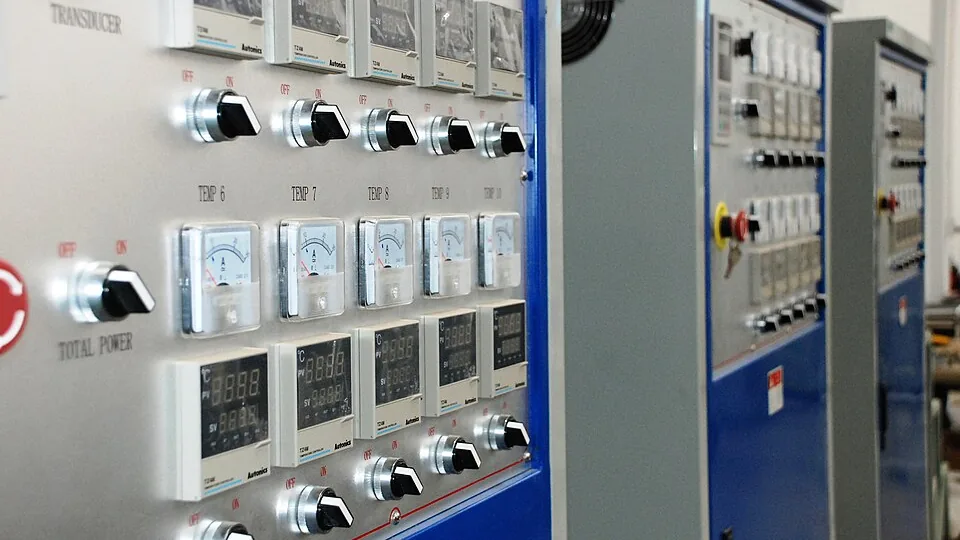
Cover photo: industrial control cabinets, by Poly-protech, via Wikimedia Commons. Licensed under CC BY-SA 4.0. The image was cropped and converted to WebP; the adapted image is shared under the same license.

