
A pneumatic cylinder extends normally when a machine is empty. Under production load, it slows down, hesitates halfway through the stroke, or fails to reach the position sensor before the PLC timer expires.
The operator may describe the symptom as "a weak cylinder." A maintenance team may immediately suspect worn piston seals. Yet the same result can arise from an exhaust restriction, an unsuitable flow-control setting, changing air supply, excessive side loading, mechanical misalignment, or the control system's interpretation of movement.
A cylinder is only one element in the motion chain. The supply, directional valve, flow controls, tubing, piston, rod, load and position feedback all influence the observed result.
The engineering task is to distinguish insufficient force, restricted movement, normal motion reported incorrectly, and a control sequence that stops the movement intentionally.
1. Begin with the actual motion symptom
"Slow cylinder" is not a sufficiently precise fault description. Several visibly similar symptoms point toward different parts of the machine.
| Observed behavior | Meaningful diagnostic question |
|---|---|
| Slow in both directions | Is a common supply, restriction or load condition involved? |
| Slow in one direction only | Do the chamber areas, exhaust paths and directional loads differ? |
| Moves normally at first, then stops | Does load, friction, available force or control state change during the stroke? |
| Jerks or moves unevenly | Could friction, inconsistent pressure or the mechanical guide system contribute? |
| Reaches the end mechanically but PLC reports timeout | Is the feedback or sequence logic interpreting the end position correctly? |
| Slows only near the end of stroke | Is the installed cushioning system influencing deceleration? |
| Fails only when other actuators move | Is a shared compressed-air supply being affected by coincident flow demand? |
These are hypotheses, not instructions to force movement or alter a pressurized machine.
2. Understand the force balance across the piston
The force of a double-acting pneumatic cylinder depends on the pressure acting on each side of the piston and the effective surface areas.
For the extending direction, a simplified ideal relationship is:
F = p₁ × A₁ − p₂ × A₂
Here p₁ and p₂ represent the pressures in the two working chambers, while A₁ and A₂ are the corresponding effective piston areas. Friction and external mechanical resistance further reduce the force available to move the load.
In the rod-side chamber, the rod occupies part of the piston area. That is why extension and retraction often have different theoretical force characteristics at the same supply pressure.
The actual motion depends on a changing balance: the pressure difference generates force, while friction, gravity, external load and mechanical constraints resist or assist it.
A regulator reading elsewhere in the machine is not enough to establish the pressure difference across the piston while it is moving.
3. Why cylinder speed depends on airflow, not pressure alone
Cylinder speed is strongly influenced by the air volume entering and leaving its chambers over time.
A simplified geometric relationship is:
v ≈ Q / A
Here v is piston speed, Q is the relevant volumetric flow at the local chamber conditions, and A is the associated piston area. In pneumatic systems, gas compressibility and changing chamber pressures mean that this is only a conceptual relationship, not an exact prediction.
A system can have an apparently adequate static pressure and still deliver insufficient flow during motion. A restrictive valve, small tubing, undersized regulator or constrained exhaust can alter the movement even when no component is completely blocked.
This is why speed and force symptoms must not be treated as interchangeable.
For the broader supply problem, see Why Does Pneumatic Pressure Drop When Several Cylinders Move?.
4. Meter-out control and the importance of the exhaust path
Many industrial pneumatic cylinders use one-way flow-control devices arranged to restrict the exhaust from the chamber being emptied. This arrangement is commonly called meter-out control.
The purpose is to regulate motion through the outgoing air rather than simply limiting the incoming supply.
Exhaust restriction can contribute to smoother movement under suitable design conditions. However, excessive exhaust resistance can increase back pressure and reduce the net force available to move the piston.
A manufacturer may specify a different arrangement for a particular device or application. The correct design is determined by the component's operating characteristics and the machine's risk assessment.
| Possible design condition | Potential behavior |
|---|---|
| Excessive restriction in an exhaust path | Slow movement or insufficient net driving force |
| Insufficient flow damping for the actual load | Unstable or unnecessarily fast motion |
| Different restrictions by direction | Extension and retraction speeds differ significantly |
| Changed component after maintenance | Previous motion behavior may no longer match the intended design |
The physical state of a flow control must never be changed as a shortcut while people or equipment are exposed to unexpected motion.
5. A cylinder can be electrically commanded but mechanically unable to move
A PLC output indicator or an energized solenoid confirms only part of the intended control chain.
For a cylinder to move as expected, several conditions must align:
Control request → directional valve response → chamber pressure difference → available force → mechanical movement → position feedback.
An electrical command does not prove that the valve has transferred air. A valve response does not prove adequate pressure at both cylinder chambers. Movement does not prove that the position sensor will correctly report the final state.
This distinction prevents a common diagnostic error: replacing the cylinder when the missing evidence is actually a command, valve action or feedback transition.
For a detailed discussion of directional-valve symptoms, see Why Does a Pneumatic Solenoid Valve Fail to Actuate?.
6. Why a cylinder can stop halfway through its stroke
A mid-stroke stop may result from a force balance that changes with position, a control decision, or a mechanical problem.
Examples include increasing mechanical resistance, a change in load direction, a guide that binds over part of the travel, a pressure limitation under demand, or a control sequence that withdraws the valve command.
The significance of the stopping position is important:
- If the cylinder hesitates at approximately the same position, a position-dependent mechanical or process condition becomes relevant.
- If the position changes from cycle to cycle, variability in load, supply or control timing may be more likely.
- If the PLC stops requesting movement before the cylinder ceases moving, the control sequence may explain the result.
- If the command remains active but the expected feedback does not arrive, the pneumatic and mechanical parts of the system deserve engineering review.
No one observation proves a specific failed component. Multiple sources of evidence should agree before a diagnosis is accepted.
7. Misalignment and side loading can imitate air-supply faults
A conventional rod cylinder is intended to produce axial force through its piston rod. Excessive lateral forces, unsuitable coupling geometry or guides that are not aligned with the cylinder's motion can increase friction and create uneven loading.
This may be visible as jerky movement, a hesitation in a repeatable portion of the stroke or accelerated wear.
SMC's cylinder documentation lists misalignment between the workpiece guide axis and cylinder axis, as well as rod deformation caused by excessive side loading, among possible explanations for poor movement.
Festo's cylinder troubleshooting documentation likewise identifies non-parallel guidance as a possible contributor to irregular piston motion.
The engineering distinction is between a cylinder that lacks pneumatic driving force and one whose load or installation introduces excessive mechanical resistance.
8. Stick-slip movement and the role of friction
Stick-slip describes motion in which resistance is initially high enough to prevent movement, then falls as the mechanism begins moving, producing a sudden displacement.
In pneumatic systems, the compressibility of air can make such behavior especially noticeable under some load and friction conditions.
Potential contributing factors include sliding-surface condition, lubrication suitability, seal friction, low available pressure differential and mechanical loading.
The presence of stick-slip does not justify adding oil to every machine. Cylinder lubrication and air preparation must match the manufacturer specification. Some cylinders are designed for operation with clean, non-lubricated compressed air.
A symptom such as uneven motion is therefore evidence for several possible friction-related mechanisms, not a direct order to replace the seals or lubricate the unit.
9. Cushioned end positions are different from mid-stroke faults
Many pneumatic cylinders include cushioning or associated external devices intended to reduce kinetic impact near the end of travel.
A correctly designed cushioning arrangement decelerates the moving assembly before the mechanical end position is reached. Its behavior depends on cylinder type, moving mass, operating speed and manufacturer design.
If the cylinder slows predominantly near the end of its stroke, the cushioning arrangement is a relevant possible explanation.
If it stops halfway through travel, ordinary end-position cushioning is usually less directly relevant unless the specific cylinder or machine architecture includes special control features.
| Symptom | Relevant engineering distinction |
|---|---|
| Slow only over the last part of travel | End-position deceleration or process-specific braking |
| Rebound or hard impact at end position | Moving energy and cushioning design |
| Hesitation in the middle of the stroke | Position-dependent load, friction, supply or sequence |
| Uneven travel over the full stroke | Friction, flow stability, load or component condition |
Manufacturer limits for kinetic energy and cushioning performance must be respected. A standard cylinder does not automatically serve as a shock absorber for any connected load.
10. Seal wear is one possibility, not the automatic conclusion
Piston and rod seals can wear, become damaged or perform poorly under unsuitable operating conditions. Their condition can affect leakage, friction and the cylinder's ability to maintain the required pressure difference.
However, a slow cylinder is not conclusive evidence of leaking seals.
A mechanically constrained cylinder or one affected by exhaust back pressure can display similar symptoms. The relationship between the observed motion, load and available pressure should be understood before seal wear is identified as the root cause.
Internal repairs and service require approved isolation procedures and the manufacturer's maintenance instructions. General descriptions of symptoms are not a substitute for those procedures.
11. Position feedback can report failure when motion is normal
Industrial pneumatic machines often use magnetic cylinder switches, proximity sensors or another form of end-position feedback.
An actuator may physically reach its intended position yet the controller still report a cycle timeout. A failed, missing or delayed feedback transition can prevent the next sequence step even when the pneumatic movement itself is correct.
A useful distinction is:
| Observation from existing machine records | Possible interpretation |
|---|---|
| Motion completion is recorded, but a particular sensor remains inactive | Position feedback or signal interpretation may be involved |
| PLC output becomes inactive before the expected position is reached | Control or interlock sequence deserves review |
| Sensor state changes at an unexpected time | Feedback location, timing or signal quality could matter |
| Both movement and feedback are delayed | Mechanical, air-supply or command timing may be involved |
The PLC's own event history and the machine's approved documentation help separate process feedback from physical movement.
12. A reconstructed case: actuator slows only with the product installed
Consider a packaging machine with a double-acting pneumatic cylinder that moves a small workpiece holder.
Without product, the actuator finishes its movement inside the expected cycle time. During production, the movement becomes slower and the machine occasionally reports a timeout.
The problem is described as a defective cylinder. Yet the production records show that the load changed when a heavier product format was introduced, while the pneumatic and mechanical design remained unchanged.
A supported engineering investigation would compare the new load and motion requirements with the cylinder's available force, guiding arrangements and the complete pneumatic supply path.
The lesson is that a difference between loaded and unloaded movement does not automatically identify a failing cylinder. It may reveal that the design margin or mechanical loading assumptions have changed.
This is an illustrative teaching example, not a documented factory incident.
13. A reconstructed case: the cylinder reaches the end but the PLC disagrees
In a second illustrative machine, the actuator appears to reach its end position during an automatic sequence, but the PLC registers an incomplete-stroke fault.
Archived sequence events indicate that the valve command remained active and the machine reported movement completion through a separate monitoring channel. The expected end-position sensor signal did not change within the programmed time.
That observation moves attention toward feedback and sequence interpretation instead of immediately suggesting an internal air leak.
However, it is still necessary to determine whether the physical position was truly reached and whether the feedback evidence is trustworthy.
Lesson: Separate an actual motion failure from an incomplete or inaccurate report of motion.
14. Why the timing of a fault is useful
Different patterns can help establish a narrower set of hypotheses:
- Only during the first production cycle: Startup conditions and changing initial states may matter.
- After many repeated cycles: Thermal, wear-related or changing process conditions may be relevant.
- At a specific stroke position: Mechanical geometry or position-dependent loading deserves attention.
- When another actuator starts: Shared airflow and pressure dynamics may contribute.
- Only after a product change: The load, process timing or mechanical arrangement may have changed.
- Immediately after maintenance: A documented component, configuration or assembly change may be significant.
A timing pattern is evidence of correlation, not proof of causation. The objective is to explain the observed mechanism with several independent indications.
15. A structured way to classify the cause
Before a conclusion is written, the symptom can be grouped into six diagnostic domains.
| Domain | Main question |
|---|---|
| Control command | Did the machine request motion for the expected duration? |
| Directional valve | Did the control system receive the expected valve-state information? |
| Air supply and exhaust | Was the flow path capable of supporting the required movement? |
| Cylinder | Could the actuator produce the required motion within its design limits? |
| Mechanical load and guidance | Did resistance or loading change with position or product? |
| Position feedback | Did the monitoring system correctly detect movement and completion? |
This structure is intended for interpreting approved diagnostic records and organizing authorized engineering work. It is not an instruction to perform live adjustments or defeat machine safeguards.
16. What a useful maintenance report should document
A good report allows another engineer to distinguish the observed symptom from the suspected and ultimately verified cause.
| Report item | Useful content |
|---|---|
| Cylinder and machine identity | Installed model and machine station |
| Symptom description | Slow, irregular, incomplete or incorrectly reported stroke |
| Direction and position | Extension or retraction; repeatable position if known |
| Operating context | Product type, load and simultaneous actuator motions |
| Available diagnostic history | Controller states, error records and existing trends |
| Mechanical design | Known loading and guide arrangements |
| Component specifications | Cylinder, valve, flow controls and cushioning design |
| Findings and limitations | Verified cause, excluded hypotheses and remaining uncertainty |
Documentation should also establish how the result was accepted through the site's approved verification process.
17. Common diagnostic mistakes
- "A slow cylinder must have bad seals." Mechanical friction, limited flow and supply problems can create similar symptoms.
- "The PLC output is active, so the pneumatic system must be healthy." Command status does not prove motion.
- "Adequate regulator pressure guarantees sufficient cylinder force." Dynamic chamber pressure and back pressure matter.
- "Extension and retraction should always perform identically." The rod changes effective piston area and load conditions.
- "Every hesitation is caused by cushioning." Ordinary end-position cushioning is not the primary explanation for all mid-stroke symptoms.
- "The actuator failed because the end switch did not change." Motion and feedback are separate evidence streams.
- "Increasing the pressure proves the root cause." Unjustified changes may hide the problem and create hazards.
- "A new cylinder will solve a misaligned guide." The underlying mechanical arrangement may remain unchanged.
Technical conclusion
A pneumatic cylinder's movement is the result of an entire engineering system, not simply the health of the piston and seals.
Pressure difference produces force; air movement influences speed; load and friction resist motion; cushioning modifies end-position behavior; and feedback tells the controller whether the intended action is complete.
When a cylinder becomes slow, jerky or unable to finish its stroke, the most effective analysis separates these mechanisms rather than treating every symptom as a defective actuator.
For related problems, see Why Does Pneumatic Pressure Drop When Several Cylinders Move?, Why Does a Pneumatic Solenoid Valve Fail to Actuate? and Why Does a Machine Stop Without an Alarm?.
Technical references
- SMC — Compact Cylinder Operation Manual, including the basic meter-out circuit and troubleshooting information on alignment, seals and poor movement.
- Festo — Pneumatic Cylinders: Product Information, for application-specific cylinder data, mounting and motion design.
- ISO 4414:2010 — Pneumatic Fluid Power: Safety Requirements, for relevant system-level safety considerations. Consult the applicable edition and local requirements.
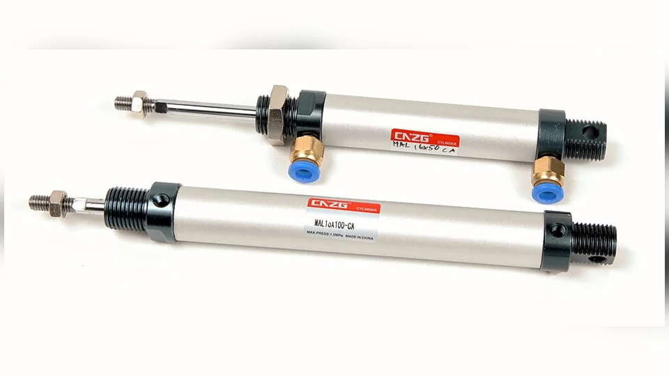
Cover photograph: two industrial pneumatic cylinders, by Grummelbacke, via Wikimedia Commons. Licensed under CC BY-SA 4.0. The photograph has been resized, centered on a softly blurred background, and converted to WebP. This adapted image is distributed under the same license.

