
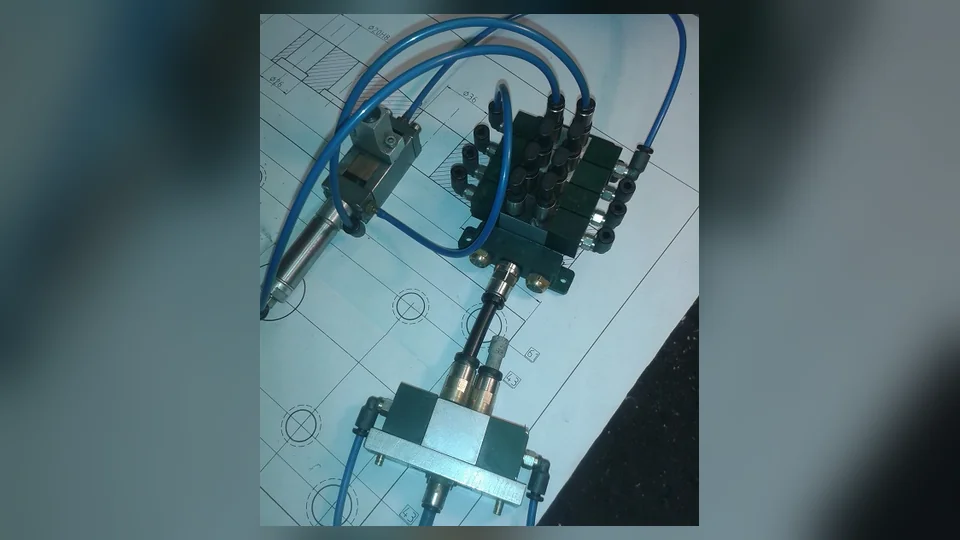
A machine stops because a pneumatic cylinder does not reach its expected position. The operator hears an air hiss near the valve manifold. The pressure gauge on the filter-regulator appears normal, and the PLC output indicates that the valve is energized.
Which component is defective?
There is not enough evidence to answer.
The hiss could be normal exhaust air, a leakage path through a valve, an external connection leak or air escaping from an actuator through another component. The pressure reading may reflect an idle condition rather than the pressure available during motion. The PLC output indicates a control request, but does not establish that the spool changed position or that the actuator moved.
A reliable investigation follows the chain of command, pressure, flow, motion and feedback. It keeps competing explanations separate until the available evidence identifies the first meaningful deviation.
1. Define what actually failed
The description "pneumatics problem" covers several very different events. It is useful to divide the symptom into a specific failure family.
| Observed symptom | Main question | Examples of possible explanations |
|---|---|---|
| Continuous unexpected air consumption | Where is air leaving or bypassing the system? | External leakage, valve seat leakage, a circuit held in an unusual state |
| Pressure collapses during movement | Can the supply path support the demand? | Filter, regulator, tubing restriction, combined actuator flow |
| Coil commanded but no actuator motion | Was air actually routed and was force available? | Command path, valve mechanism, pilot supply, mechanical load |
| Actuator moves slowly or unevenly | What limits speed or resists motion? | Exhaust restriction, flow control, friction, misalignment |
| Cylinder reaches its position but PLC reports a fault | Did the controller receive valid completion feedback? | Position sensing, input wiring, sequence interpretation |
| Fault appears only at a certain machine state | What changes at that precise point? | Different valve state, changed load, coincident demand, sequence timing |
This classification prevents a maintenance team from turning one symptom into an unsupported conclusion about a particular part.
2. Read the pneumatic circuit as a functional system
A typical pneumatic arrangement may include a compressed-air source, isolation and safety-related functions, air preparation, a directional valve, flow controls, an actuator and sensors reporting the result.
The actual sequence and components depend on the machine's design.
Supply → Air preparation → Directional control → Flow paths → Actuator → Position or process feedback
The schematic explains what each valve position connects and what happens to the air entering or leaving an actuator chamber.
This is important because a port that exhausts air during normal operation is not necessarily leaking. The function of the installed valve determines which exhaust paths are expected.
Before interpreting an air-related symptom, identify the documented valve arrangement, the active sequence state and the expected direction of actuator movement.
3. An audible hiss is not a diagnosis
Compressed air often produces audible sound during ordinary exhaust. Some valves and manifolds can also contain silencers or exhaust treatment devices.
A continuous hiss outside the expected exhaust phase may justify investigation, but its location alone does not prove which component has failed.
The audible source can be displaced from the initiating fault. For example, depending on the valve and circuit arrangement, an internal cylinder leakage path might make itself noticeable through a valve exhaust port.
Similarly, a valve exhaust sound could be associated with normal switching, a valve sealing condition or another path through the connected circuit.
The important engineering distinction is between expected exhaust, external leakage and internal bypass leakage. They should not be treated as interchangeable.
4. External leaks and internal leakage have different consequences
An external leak allows compressed air to escape from a pressurized component or connection to the surrounding environment. Possible locations include fittings, tubing, connectors, regulator housings and actuator seals.
An internal leak allows air to pass between intended chambers or passages within a device. Examples include leakage across a cylinder piston seal or through an internal valve sealing arrangement.
These categories can produce different symptoms.
| Leakage category | Possible system effect | Limitation of the observation |
|---|---|---|
| External fitting or tubing leak | Increased consumption and possible local pressure reduction | The size and effect are not proved by sound alone |
| External actuator seal leak | Air loss near an actuator and possible performance reduction | A mechanical or supply issue may also be present |
| Internal cylinder leakage | Reduced effective pressure difference and force under some conditions | Behavior depends on load, valve state and chamber pressures |
| Internal valve leakage | Unintended flow between valve passages | Requires understanding the valve's intended port connections |
| Regulator or relief-related exhaust | Air release under a particular operating condition | Some venting is part of normal component behavior |
A leaking component does not necessarily explain the entire machine fault. A small, longstanding leak may coexist with a new timing or load problem that actually caused the production stop.
5. Pressure at rest and pressure during motion are different evidence
The gauge on a machine's regulator may return to the target value when the pneumatic circuit is inactive. That reading is useful but incomplete.
When several actuators move, pressure losses through filters, regulators, distribution lines and valves may become significant.
This is why a fault that appears during the production cycle cannot be judged entirely from an idle pressure reading.
Consider the following hypothetical trend, intended only to demonstrate interpretation:
| Machine state | Existing upstream reading | Existing downstream reading | Possible significance |
|---|---|---|---|
| Idle | 6.3 bar | 6.0 bar | Static pressure appears established |
| One actuator operating | 6.2 bar | 5.8 bar | A modest flow-related decrease |
| Multiple actuators operating | 6.1 bar | 4.8 bar | A substantial dynamic loss |
| Idle again | 6.3 bar | 6.0 bar | Supply path recovers after demand |
These readings do not establish a defective regulator. A restriction or capacity limitation elsewhere in the path could contribute.
The important evidence is the relationship between pressure, timing, flow demand and sensor location.
6. A valve's electrical status is not its pneumatic status
An activated PLC output or a lit connector LED indicates only part of the control chain.
A pneumatic valve may require a correct electrical command, functioning coil or driver, an operative mechanical switching element and, for pilot-operated designs, suitable pilot conditions.
Even if a valve shifts, the expected actuator motion still depends on the connected air path and available force.
| Available indication | What it may establish | What it does not establish |
|---|---|---|
| PLC output commanded | The control application requested the output | The field valve switched successfully |
| Connector LED on | Some voltage or output indication is present | Correct power at the coil under the intended load |
| Valve-state indication present | The valve or its control reports a selected state | Air reaches the actuator at the required flow |
| Actuator-position signal changes | The monitoring system reports a position | All other process conditions are satisfactory |
| Actuator moves but stops early | Motion began | The valve or actuator itself must be defective |
This distinction is central to fault diagnosis: command, actuation and feedback are different stages, and each can produce misleading evidence about the others.
7. Why directional-valve function matters
Directional valves may be described by their number of ports and positions, such as 3/2 or 5/2.
Their behavior also depends on actuation and return arrangements: spring-return, bistable, pneumatic pilot and other configurations are not equivalent.
For example, a bistable arrangement may remain in its last selected state rather than returning to a default state when a command disappears. A pilot-operated valve may have requirements that differ from a directly operated valve.
An analysis that assumes the wrong rest state can wrongly classify normal exhaust, unexpected pressure or delayed motion as a component failure.
Use the installed device's documented symbol and operating principle rather than inferring behavior from the external appearance of the coil.
8. Flow restriction can look like leakage
A restricted flow path can make a cylinder slow down. A leakage path may also reduce effective performance or available pressure.
These problems can look similar from the machine operator's viewpoint, but the physical mechanisms differ.
Possible restrictions include a loaded air filter, an unsuitable regulator, undersized tubing, a restrictive fitting, an exhaust-flow control, or a valve/manifold with insufficient flow capacity for the application.
Unlike a leakage path, a restriction does not necessarily cause continuous air loss. Its effect may become visible only while air moves through it.
Diagnostic principle: A symptom that appears only during high flow demand should not automatically be interpreted as evidence of a permanent leak.
9. Mechanical faults can be misreported as pneumatic faults
Cylinders are connected to mechanisms, guides and moving loads. Excessive side force, misalignment, binding or changes in process load can prevent expected movement even when the pneumatic supply and valve perform their intended functions.
SMC documentation lists misalignment, excessive lateral loading, insufficient pressure, internal leakage and unsuitable circuit design as different possible explanations for abnormal cylinder operation.
The mechanical system must therefore remain within the scope of a pneumatic fault investigation.
A machine may stop because the cylinder cannot overcome the connected load, rather than because a pneumatic component has lost its ability to direct air.
10. Feedback errors may imitate failed movement
A PLC commonly decides that a pneumatic operation is complete only after it receives the required position or process feedback.
If the physical motion finishes but the expected sensor input does not change, the controller may report a cycle timeout.
Conversely, an input may change while the machine has not reached the intended mechanical condition if the sensor is incorrectly associated with the process state.
The distinction is between the actual physical event and the controller's available evidence of that event.
A useful diagnostic record includes the expected sequence state, command status, recorded completion signal and relevant machine-condition history.
11. Separate a symptom from its first abnormal event
A stopped conveyor, gripper or transfer mechanism is usually the most visible symptom, but it may not be the initiating failure.
A downstream pneumatic cylinder may fail to report completion. The controller then withdraws an upstream conveyor command, and the operator sees the conveyor stop.
Replacing the conveyor motor in this scenario would address a secondary symptom rather than the cause of the stop.
Event chronology matters:
Expected movement → missing or delayed feedback → sequence timeout → upstream stop.
This pattern is conceptual. Actual cause must be supported by the machine's recorded diagnostic history and functional description.
12. Use a fault matrix before choosing a cause
The following matrix organizes the types of evidence available from normal operating records and approved diagnostics.
| Evidence pattern | Stronger hypothesis | Alternative to keep in view |
|---|---|---|
| Pressure falls only when several axes move | Shared supply capacity or flow restriction | Unexpected simultaneous leakage or consumption |
| One actuator becomes slow in one direction | Direction-specific load or airflow limitation | Valve behavior or actuator condition |
| Continuous hiss with little process activity | Unexpected leakage or venting path | Normal regulator or valve exhaust behavior |
| PLC requests movement but no completion signal follows | Motion, control or feedback chain failure | Incorrect sequence expectation |
| Actuator moves correctly but timer still expires | Feedback or logic interpretation | Intermittent mechanical timing issue |
| Several pneumatic stations fail together | Shared supply, air-quality or control condition | Coincident but separate component failures |
| Symptom appears after product or cycle change | Changed load or instantaneous demand | An existing marginal component becoming visible |
The matrix does not provide a direct repair instruction. It gives engineers a way to avoid treating a single symptom as proof.
13. Reconstructed case: an air hiss that pointed to the wrong valve
Consider an illustrative assembly machine with a double-acting cylinder and a directional valve.
Maintenance personnel hear continuous air escape near the manifold and suspect a damaged valve. The cylinder also fails to develop the expected force during one part of its cycle.
The system documentation shows that the observed exhaust path is connected to the actuator chamber in the relevant valve state. This means the sound may reflect air passing through the actuator circuit, not necessarily a defective exhaust port.
The engineering interpretation remains open until the documented valve state, possible chamber leakage and actual process history are evaluated together.
The lesson is not that cylinder seals are always responsible for air heard at a manifold. It is that the audible location and the physical origin of leakage may differ.
This is a reconstructed teaching example, not a report of a specific factory incident.
14. Reconstructed case: replacing the cylinder did not remove the timeout
A second illustrative machine repeatedly reports that a pneumatic transfer cylinder did not reach its end position.
The cylinder is replaced, but the fault returns on the first production cycle with the heavier workpiece format.
A review of available records shows that the original problem occurred only with the new load and when several pneumatic operations overlapped.
These facts make increased mechanical demand and the shared supply path relevant. They do not prove whether a particular valve, filter, regulator or fitting is responsible.
Replacing the actuator was not a verified correction because the evidence did not establish a failure within the actuator itself.
Lesson: A replaced component and a temporarily successful cycle do not prove the root cause was found.
15. A systematic diagnostic workflow for maintenance engineering
A useful fault investigation can be organized as a sequence of evidence-based decisions. The steps below describe analytical work using existing records and documentation; physical tests must be carried out separately under approved procedures by qualified personnel.
- Record the symptom accurately. Identify the exact motion, pressure or feedback behavior and the production conditions under which it occurs.
- Establish the intended circuit operation. Use the pneumatic schematic and the machine's functional description.
- Preserve event chronology. Determine which command, feedback or process event deviated first.
- Separate the likely physical mechanisms. Consider external leakage, internal bypass, flow restriction, supply pressure, valve action and mechanical resistance.
- Compare existing pressure and process trends. Interpret each value at its recorded location and operating state.
- Assess the controller's reported states. Distinguish command output, actual motion and completion feedback.
- Evaluate competing hypotheses. Document observations that support or contradict each explanation.
- Confirm through authorized engineering procedures. Record the validated cause, corrective action and acceptance result.
The objective is to explain the failure mechanism rather than simply obtain another successful restart.
16. What belongs in a pneumatic fault report
| Report field | Useful information |
|---|---|
| Machine and station | Exact equipment and circuit reference |
| Symptom and timing | What failed and in which sequence state |
| Pneumatic design | Valve type, actuator arrangement and relevant air preparation |
| Control evidence | Command, interlock, timeout and feedback history |
| Pressure context | Existing values with sensor location and operating state |
| Process conditions | Product, load, simultaneous actuators and recent changes |
| Hypotheses considered | Evidence for and against leakage, restriction, mechanical or control causes |
| Verified outcome | Supported root cause, approved work and acceptance evidence |
The documentation should distinguish a confirmed finding from a plausible explanation. Uncertainty is part of an accurate technical report when evidence is incomplete.
17. Seven mistakes that keep pneumatic failures recurring
- Treating every audible hiss as a broken valve. Normal exhaust and leakage can sound similar.
- Assuming a normal idle gauge proves correct pressure during motion. Dynamic demand and losses matter.
- Replacing a cylinder because it moves slowly. The restriction or load may be elsewhere.
- Confusing the PLC output with actual valve operation. Command status is not pneumatic confirmation.
- Ignoring actuator feedback. A position-signal problem can look like a failed stroke.
- Changing multiple settings at once. The causal effect of any individual change becomes difficult to demonstrate.
- Closing a case because the machine restarted. Restarting does not necessarily identify or remove the underlying condition.
Technical conclusion
Pneumatic fault diagnosis works best when air leaks, pressure limitations, valve behavior, cylinder movement and control feedback are considered as distinct but connected mechanisms.
A continuous hiss does not by itself identify a leaking component. A correct static pressure does not demonstrate adequate flow capacity. An energized coil does not prove the air path switched. And a PLC timeout does not prove that the actuator failed physically.
The most reliable engineering approach is to reconstruct the intended circuit and machine sequence, find the earliest abnormal event, and compare several independent forms of evidence before deciding what caused the failure.
For more focused explanations, read Why Does Pneumatic Pressure Drop When Several Cylinders Move?, Why Does a Pneumatic Solenoid Valve Fail to Actuate? and Why Does a Pneumatic Cylinder Move Slowly or Stop Mid-Stroke?.
Technical references
- SMC — Pneumatic Cylinder Operation Manual: Troubleshooting: separate causes of poor cylinder performance, including leakage, pressure, external loading and circuit design.
- SMC — Compact Cylinder Operating Manual: representative valve, flow-control and cylinder relationships.
- Festo — How Compressed Air Systems Work: air treatment, pressure and flow monitoring, maintenance and plant distribution.
- Festo — Sustainability Using Controlled Pneumatics: diagnostic concepts for leakage and actuator-related monitoring.
Cover photograph: functional pneumatic valve circuit, by Pneumaticklima, via Wikimedia Commons, licensed under CC BY-SA 4.0. The original image was resized, centered on a blurred background and converted to WebP; the adaptation is distributed under the same license. The pictured equipment illustrates a physical valve circuit, not a prescribed procedure for diagnosing an energized machine.

