
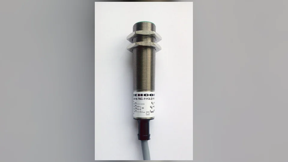
An inductive sensor detects a metal target, and its indicator lights up. The machine nevertheless reports Sensor not reached. On the PLC diagnostics screen, the associated digital input remains OFF.
The first reaction is often to replace the proximity switch. Yet a sensor can correctly detect a target and still fail to produce a signal recognized by the PLC input module.
The reason is that object detection, sensor output switching, electrical delivery of a signal, digital-input recognition and PLC application logic are distinct stages.
A useful investigation separates these stages and identifies which one the available evidence actually confirms.
1. The sensor LED is only one piece of evidence
A sensor may have a power indicator, switching-state indicator, alignment indicator, signal-strength indicator or a combination of these. The meaning of a particular LED depends on the manufacturer and model.
The presence of an LED does not necessarily establish the electrical output state, the load current capability or the signal received at the controller.
Even when the indicator explicitly reports an active switching output, it may confirm only the sensor's internal state rather than successful current flow through the complete PLC input circuit.
| Observation | What it may establish | What it does not establish |
|---|---|---|
| Power LED illuminated | The device reports a supply or operating condition | That the output is active or the PLC sees a logic 1 |
| Switching LED illuminated | The sensor reports its switching state | That current reaches a compatible PLC input |
| Input-module LED illuminated | The module reports a channel state | That every application variable uses that input as expected |
| PLC process variable remains OFF | That a particular software state is false | Which physical or logical stage caused it |
| HMI shows sensor missing | An application condition was not met | That the sensor hardware is defective |
The first engineering task is to identify which specific indicator is being observed.
2. The complete path from target to PLC logic
For a typical discrete field sensor, the functional chain is:
Target or process condition → sensing electronics → transistor/contact output → field cable and connector → input-module electrical circuit → input filtering and sampling → PLC variable → machine sequence.
This chain can fail or become unsuitable at more than one point.
For example, a correctly detected target does not prove that the sensor's output type matches the input module. A valid electrical input does not guarantee that a pulse is long enough to be captured. A correctly recognized PLC input does not prove that the application is reading the intended channel.
The symptom "LED ON, PLC OFF" therefore describes an inconsistency between observations, not a diagnosis of a particular defective component.
3. PNP and NPN are different output architectures
Many three-wire DC industrial sensors use transistor outputs described as PNP or NPN.
A PNP output, commonly called a sourcing output, supplies a positive signal to a compatible load when active.
An NPN output, commonly called a sinking output, provides a path toward the negative reference when active.
Schneider Electric and Balluff both emphasize that the choice must match the PLC input circuit and the device documentation.
| Property | PNP sensor output | NPN sensor output |
|---|---|---|
| Common description | Sourcing output | Sinking output |
| Active-state principle | Switches toward the positive supply | Switches toward the negative supply |
| Corresponding conventional PLC input | Sinking input | Sourcing input |
| Typical misunderstanding | The LED lights, but the receiving circuit is not compatible | The LED lights, but the receiving circuit expects a positive output |
Some modern input modules support both configurations or offer configurable input groups. Others have a fixed circuit architecture. The input-module data sheet, not an informal naming convention, is authoritative.
4. The terms sourcing and sinking describe complementary functions
The names can be confusing because they may refer either to the field device or to the PLC module.
A PNP sourcing sensor normally works with a sinking PLC input.
An NPN sinking sensor normally works with a sourcing PLC input.
A statement such as "the system uses sourcing inputs" must therefore be checked against the device documentation to determine whether it describes the sensor output or the input module's electrical behavior.
It is also important not to assume that a factory uses only one output type. Replacement sensors, remote I/O equipment and regional equipment variants may differ.
A proper engineering record identifies the exact output type and receiving input circuit, not merely the word "sourcing".
5. Why a replacement sensor can look healthy but not work
Consider a reconstructed manufacturing station with an inductive position sensor.
The original sensor has a PNP normally-open output. After a maintenance replacement, a mechanically compatible sensor is installed. It has the same cylindrical size and connector style, and its indicator changes when the target enters the sensing area.
However, the replacement model has an NPN output while the existing PLC input circuit was designed around the PNP signal.
The sensor electronics may be detecting the target correctly. The mismatch lies in the interface expected by the receiving circuit.
That is why matching a replacement sensor by physical dimensions and sensing range alone is insufficient.
The replacement specification must also match the relevant electrical output technology, switching behavior, supply limits, connector pin assignments and machine requirements.
This is a reconstructed educational case, not a verified incident at a specific factory.
6. Normally open and normally closed are separate from PNP/NPN
A PNP or NPN sensor can often be specified with either a normally-open (NO) or normally-closed (NC) switching behavior.
PNP/NPN describes how the transistor output electrically switches.
NO/NC describes the intended output behavior relative to the sensor's target-detection state.
They answer different engineering questions.
| Description | Question it answers |
|---|---|
| PNP | Does the active output source current toward a load? |
| NPN | Does the active output sink current from a load? |
| NO | Is the designated switching output normally inactive before the target condition? |
| NC | Is the designated switching output normally active before the target condition? |
The exact normal state and indicator function must come from the installed device's specification.
An NO/NC mismatch can invert the observed machine signal even if the sensor and input module are otherwise electrically compatible.
7. A functioning transistor output still needs a complete circuit
A PLC digital input does not recognize a signal merely because a voltage appears somewhere on a disconnected or incompatible conductor.
The input circuit has specified voltage and current requirements and a defined electrical reference.
Potential engineering causes of "sensor active, input OFF" include:
- An incompatible PNP/NPN pairing.
- A missing or unsuitable supply/reference arrangement.
- A field connector or cable discontinuity.
- An input group whose common connection does not correspond to the intended design.
- A module channel that is configured or addressed differently from the documented expectation.
These are categories for interpreting drawings and authorized inspection evidence. They are not instructions to reconnect or change live conductors.
8. Input thresholds are not universal
A PLC digital input recognizes electrical ON and OFF states according to the input module's documented thresholds and current characteristics.
For example, Siemens technical specifications for an S7-1200 CPU 1211C list a nominal 24 V DC digital-input configuration, with a stated minimum logic-1 input and maximum logic-0 input for that particular product.
Those values are model-specific, not universal numbers for all PLCs.
| Specification parameter | Why it matters |
|---|---|
| Nominal input voltage | Establishes the intended electrical operating range |
| Minimum logic-1 threshold | Determines what the module accepts as an ON signal |
| Maximum logic-0 threshold | Determines what the module accepts as OFF |
| Input current characteristic | Helps establish compatibility with field output devices |
| Input group/reference arrangement | Determines the intended electrical interface |
| Filter behavior | Determines which signal transitions the controller may accept |
A sensor output that appears plausible in isolation may still not satisfy the receiving module's requirements.
The engineering comparison must use the actual device and module part numbers.
9. The 24 V supply can change during machine operation
A sensor may operate normally during idle conditions and become unreliable when several loads switch.
An industrial 24 V DC distribution system can experience voltage changes because of dynamic load demand, unsuitable capacity, conductor losses, distribution protection or a fault condition.
An LED that remains illuminated does not establish that the sensor's supply and output behavior remained within requirements throughout a brief disturbance.
Relevant evidence may include existing power-supply event logs, controller input history, known supply loading and the timing of affected devices.
A disturbance that appears simultaneously on several field inputs is a different diagnostic pattern from one isolated failed sensor.
For a separate discussion of dynamic control-power conditions, see Why Does a 24V DC Power Supply Drop When Solenoids Switch?.
10. Sensor switching speed and PLC input filtering are not the same
A proximity sensor may respond quickly to a passing target, but the receiving PLC input can have an electronic filter intended to reject brief disturbances.
A filter that is suitable for a slow mechanical position sensor may not be suitable for a fast event signal.
Siemens documentation describes configurable digital input filtering and notes that short input transitions may not be recognized if their duration does not satisfy the configured behavior.
That means a sensor's switching LED can visibly indicate normal detection while the corresponding PLC process-image bit does not register the event.
However, an observer's visual impression of an LED flashing is not precise timing evidence. Existing event records and the system's documented design are more reliable.
Important: Modifying input filtering can affect machine behavior and must be treated as an authorized control-system design change rather than a casual fault-finding shortcut.
11. A short pulse can disappear between PLC samples
Many PLCs read process inputs according to a scan or task execution model.
A field input that changes rapidly may not remain active long enough to be visible through the ordinary cyclic input image, depending on hardware, filter settings and task timing.
Some controller families support dedicated pulse-catch, edge-event or high-speed input functions. Siemens documents pulse catch for the S7-1200 and also states that filtering applies before pulse capture in the relevant input path.
Those functions are platform- and configuration-specific.
The correct engineering question is whether the sensor's expected event duration and the PLC input acquisition method are compatible.
A fast-moving object does not automatically require a defective sensor to produce a missed PLC event.
12. An input-module LED and an application bit can disagree
When the physical input module indicates an active signal but a program variable remains false, the problem may not be in the sensor.
Possible explanations include:
- Incorrect program address or channel mapping.
- A different physical module or remote I/O station than the drawing identifies.
- A software variable that is derived or conditioned rather than directly linked to the input.
- A required mode or permissive that remains false.
- A process-image, task or timing effect.
- An HMI indication that shows a different variable or stale information.
A field input and a machine-state indicator are not necessarily the same software object.
A reliable diagnostic explanation therefore distinguishes the physical channel state, the PLC input image and the application condition.
13. Remote I/O adds another point of possible failure
In distributed automation, a sensor may connect to an input module mounted near the machine. That module communicates with the main PLC over an industrial network.
The remote input module may see a channel state while the controller reports that its connection to the station is degraded or unavailable.
This creates another important distinction:
Sensor output present → remote input module recognizes it → network transfers valid input data → PLC application consumes the data.
A problem in any one stage can affect the final machine response.
Existing remote I/O status, channel diagnostics, connection history and controller event logs can help distinguish a field problem from a communication problem.
An active Ethernet link LED alone does not establish that valid input updates are reaching the controller.
14. Two-wire sensors do not behave exactly like three-wire sensors
Some proximity sensors use two-wire connections and derive their operating power through the connected circuit.
This can introduce electrical characteristics, such as residual current in an OFF state or voltage drop in an ON state, that need to be compatible with the receiving device.
The appropriate interpretation differs from that of a conventional three-wire PNP or NPN transistor output.
A replacement choice based only on sensing distance and shape can therefore introduce an interface mismatch, even when both sensors appear to operate.
Consult the actual sensor and input-module specifications. Do not generalize an electrical diagram intended for a three-wire sensor to all two-wire devices.
15. IO-Link and configurable sensors require extra context
Some modern industrial sensors provide an IO-Link interface or a configurable switching output.
A device may support process data, diagnostic events, configurable switching points or multiple operating modes.
A channel that is used as an IO-Link communication path is not always equivalent to a conventional discrete transistor output under every configuration.
The engineering record should therefore identify not only the sensor model but the selected operating mode and the connected master or PLC interface.
An IO-Link device that reports valid sensor diagnostics does not, by itself, establish that an unrelated discrete input should become active.
16. Reconstructed case: the fast indexing sensor that was missed
Consider a machine that indexes products rapidly past a proximity sensor.
The sensor's output is documented as compatible with its PLC input module. During a slow production mode, the detection state is recorded correctly. At higher speed, the machine occasionally misses a product and later reports a sequence timeout.
The first hypothesis is an intermittent sensor failure.
However, the process history shows that the relevant target is present for a shorter interval at the higher machine speed. The documented input configuration uses a filter and acquisition method designed for a longer event.
The evidence suggests a signal-duration and input-acquisition mismatch, not necessarily a failed proximity switch.
The engineering remedy requires an authorized design assessment of the complete sensing, acquisition and sequence requirements. It is not established by simply increasing a timeout or bypassing an input.
This case is reconstructed for education and does not describe a particular factory.
17. Compare the different observable states
| Observed state | More useful question |
|---|---|
| Sensor power indicator ON, switching indicator OFF | Is the expected sensing condition actually active? |
| Switching indicator ON, input module OFF | Is the electrical output compatible with the receiving module and reference system? |
| Input module ON, controller process bit OFF | Is the channel mapped, sampled and communicated as expected? |
| Controller input ON, machine permissive OFF | Which additional application condition remains unmet? |
| Input normally works but short events disappear | Are the event duration and input acquisition method compatible? |
| Several field sensors fail together | Is a shared supply, remote I/O or communication condition involved? |
| HMI reports OFF, PLC input recorded ON | Is the HMI reading the intended and current variable? |
This is a diagnostic reasoning table, not a physical testing sequence. The presence of one state does not prove that the remaining stages are healthy.
18. The value of event chronology
A common mistake is to interpret the final alarm as the first failure.
In a reconstructed transfer station, a target-detection transition is not captured by the controller. The PLC remains in its waiting step, and a timeout later appears on the HMI.
The operator reports a cylinder-position problem because that is the last visible machine operation.
A better reconstruction separates:
Expected target detection → missing recognized input transition → unsatisfied sequence condition → timeout alarm.
This does not prove a sensor fault. It identifies the earliest abnormal stage supported by the records.
For the broader logic explanation, see Why Does a PLC Sequence Get Stuck on One Step?.
19. Maintenance records should identify the complete interface
A useful sensor-related maintenance record contains more than "sensor replaced".
| Record field | What it should identify |
|---|---|
| Sensor manufacturer and model | Exact device being used |
| Sensing principle | Inductive, photoelectric, capacitive or other |
| Electrical output | PNP, NPN, contact, two-wire or configurable |
| Switching behavior | NO/NC and relevant configuration |
| Supply requirements | Manufacturer-approved operating range |
| Connector/interface | Exact documented pin assignment and interface type |
| PLC input module | Exact model, input group and compatible signal type |
| Event behavior | Expected pulse duration and acquisition requirements |
| Signal mapping | Physical input channel and application variable |
| Validation evidence | Authorized acceptance result and any remaining uncertainty |
This information helps prevent replacement with a mechanically similar but electrically incompatible part.
20. Common mistakes in sensor-to-PLC fault diagnosis
- "The LED is ON, so the PLC must see the input." LED indication and input recognition are separate functions.
- "PNP and NPN are interchangeable." They provide different electrical output behavior.
- "Sourcing means the same thing for sensors and PLC modules." Source and sink roles are complementary.
- "Normally open tells me whether the sensor is PNP." NO/NC and PNP/NPN describe different properties.
- "The same connector guarantees the same pin assignment." Device documentation must establish compatibility.
- "A 24 V system always accepts any voltage close to 24 V." Input thresholds and current requirements are model-specific.
- "A sensor that works at low speed must also work at high speed." Pulse duration and acquisition timing matter.
- "A PLC input indicator proves the application uses that channel." Mapping and software conditions may differ.
- "All proximity sensors are three-wire devices." Two-wire and IO-Link arrangements require separate consideration.
- "Changing the PLC filter is a harmless test." Such changes can affect machine operation and require engineering approval.
Technical conclusion
An illuminated proximity-sensor indicator is evidence about the sensor, not proof of a completed PLC input chain.
A reliable explanation distinguishes object detection, sensor output type, electrical interface compatibility, input recognition, acquisition timing, remote I/O communication and application logic.
A PNP/NPN mismatch can leave the sensor apparently healthy while the PLC does not recognize its output. A correctly interfaced sensor can also produce a signal too brief for the configured input path. And a correctly recognized input may still fail to satisfy a separate sequence condition.
The best engineering outcome is a documented and verified cause, not a component replacement selected only because its LED appears normal.
For related subjects, see Analog Signals & Troubleshooting, Why Does a 24V DC Power Supply Drop When Solenoids Switch? and Why Does a PLC Sequence Get Stuck on One Step?.
Authoritative references
- Schneider Electric — Difference Between PNP and NPN Three-Wire Sensors: sensor output architectures and their compatibility with sourcing or sinking PLC input cards.
- Schneider Electric — PNP and NPN Sensor Connection Principles: switching output and load/input circuit behavior.
- Balluff — Fundamentals of Automation: NPN vs PNP: sensor switching technology and NO/NC terminology.
- Siemens — S7-1200 CPU 1211C Digital Inputs and Outputs: example of model-specific digital-input thresholds, current characteristics and filter options.
- Siemens — S7-1200 Programmable Controller System Manual: digital input filtering, pulse capture and the relationship between input changes and scan-based acquisition.
Cover photograph: industrial inductive proximity sensor by Ekbsensor, Wikimedia Commons, under the Creative Commons Attribution–ShareAlike 4.0 license. The image was resized, placed over a softly blurred background and converted to WebP; the adapted cover is distributed under the same license. The photograph illustrates sensor hardware and not the reconstructed machine cases.

