
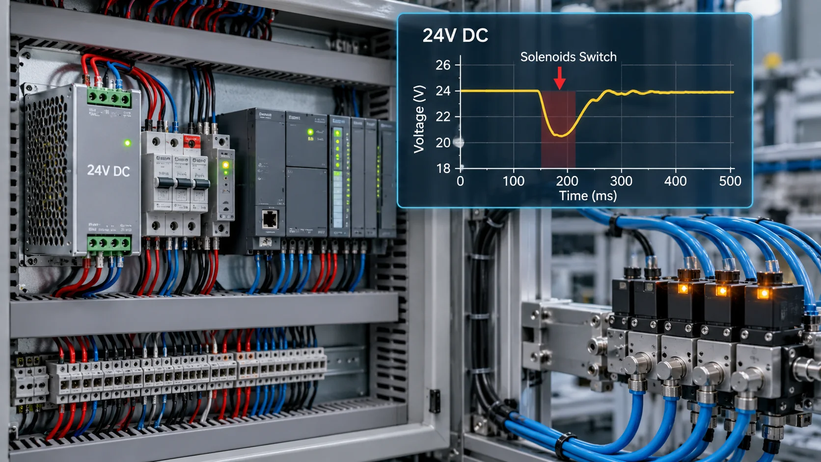
# Why Does a 24V DC Power Supply Drop When Solenoids Switch?
Understanding voltage collapse, transient loads, wiring losses, and the hidden causes of PLC resets.
By Veselin Madzharov
The PLC is running. The sensors are responding. The power supply shows 24 volts.
Then three pneumatic valves switch at almost the same moment.
The HMI briefly loses communication. A remote I/O module restarts. The operator sees a collection of alarms that appear to have nothing in common.
After restarting the machine, everything works normally.
Maintenance checks the power supply. The meter reads 24.1 V.
The power supply is declared healthy.
But the most important question has not been answered:
What happened to the voltage during the few milliseconds when the machine failed?
A control supply can show a perfectly normal voltage before and after an event while failing to maintain adequate voltage during that event.
This distinction is fundamental to diagnosing industrial 24V DC systems.
1. A 24V supply is not an unlimited energy source
Industrial 24V DC power supplies have defined operating limits.
Consider a switching power supply rated at 24 V, 5 A.
Its nominal continuous output power is:
P = U × I = 24 × 5 = 120 W
That rating does not mean the supply can deliver any current demanded by the connected equipment.
It also does not mean that its output behavior will be identical under every overload condition.
Depending on the design, an overloaded supply may:
- Limit its output current.
- Allow its voltage to decrease.
- Provide additional current temporarily.
- Enter a repeating protection-and-recovery cycle.
- Shut down until a specified recovery condition is met.
These behaviors are determined by the manufacturer's design and specifications.
A supply may therefore remain healthy while the connected control system becomes unreliable.
The fundamental error is treating nominal voltage as proof of adequate dynamic capacity.
2. Why solenoids expose hidden power problems
Pneumatic solenoid valves are commonly connected to the same 24V network as sensors, relays, PLC equipment, and remote I/O.
When a solenoid is energized, it adds electrical demand to the distribution system.
The exact current profile depends on its coil design and associated electronics. Some devices have relatively straightforward DC coil characteristics; others include electronic drivers or current-reduction circuits.
The important consideration is the combined behavior of all connected loads.
Imagine a machine with the following illustrative current demands:
| Equipment group | Current |
|---|---|
| PLC, HMI, and network electronics | 2.1 A |
| Sensors and control relays | 1.1 A |
| Four solenoid valve assemblies | 2.2 A |
| Total when all are active | 5.4 A |
The power supply is rated at 5 A.
With the valves inactive, the load is approximately 3.2 A.
Everything appears normal.
When all four valve assemblies become active, the total increases to 5.4 A.
The connected demand now exceeds the nominal continuous rating.
Whether this creates an immediate failure depends on the power supply's permitted overload characteristics, duration, temperature, and actual operating conditions.
Nevertheless, the example shows why a control cabinet can operate correctly for most of the production cycle and become unstable only during certain sequences.
Average current consumption is not the same as maximum simultaneous demand.
3. Why the PLC may restart before the power supply shuts down
Different electronic devices have different operating-voltage limits.
A PLC, an Ethernet switch, a sensor, and a solenoid valve do not necessarily respond in the same way to an undervoltage event.
During a temporary voltage reduction:
- A PLC may reset if its supply falls below its specified operating range.
- A communication module may restart and later reconnect.
- A sensor may stop producing a valid output.
- A relay or valve may release or fail to operate correctly.
- An HMI may report secondary alarms after communication is lost.
The fault sequence can become misleading.
A network communication alarm may appear first in the operator's view even though the original event was a power disturbance.
The machine may then generate additional alarms because devices disappear from the control system.
The first visible alarm is not necessarily the first physical failure.
This is why time-correlated supply diagnostics, PLC events, and load commands are more useful than a single voltage reading after the machine has stopped.
4. The power supply may not be the defective component
Suppose the power supply maintains 24.0 V at its terminals.
A field-mounted load nevertheless experiences a lower voltage.
This can result from resistance in:
- Supply conductors.
- Return conductors.
- Terminal connections.
- Connectors.
- Protection devices.
- Distribution assemblies.
The basic relationship is:
Voltage drop = Current × Total circuit resistance
Consider an illustrative branch circuit with a combined supply-and-return resistance of 0.7 ohm.
At 2 A:
ΔV = 2 × 0.7 = 1.4 V
If the source remains at 24.0 V, the corresponding load voltage is approximately:
24.0 − 1.4 = 22.6 V
That value may be acceptable for one device and unacceptable for another, depending on the manufacturer's specified operating range.
At lower branch current, the voltage loss is smaller. As the current increases, the voltage loss increases.
The key point is that a branch with excessive resistance can create a problem even when the central power supply itself is adequately rated.
A normal reading at the supply terminals does not establish the voltage available at every load.
5. Shared return conductors can make faults appear unrelated
The positive side of a 24V circuit receives considerable attention during troubleshooting.
The return path is sometimes treated as though it has no electrical significance.
That is a mistake.
Current must return through a complete circuit. A shared return conductor has resistance, just like the positive conductor.
When several devices use the same return path, changes in their combined current can create changes in the voltage difference between different points in the distribution network.
This may affect equipment that depends on a particular voltage reference.
For example, a sensor and an electronic input module may behave unexpectedly if the voltage available across the actual device terminals moves outside the interface's permitted conditions.
A high-resistance return connection can also cause several otherwise unrelated circuits to become unstable together.
This is one reason that intermittent faults affecting multiple sensors deserve a system-level investigation rather than immediate replacement of individual sensors.
6. Voltage collapse and switching transients are different problems
Not every fault that occurs when a solenoid switches is caused by an overloaded supply.
An inductive coil stores energy in a magnetic field.
When its current changes, the resulting electrical transient can interact with the switching device and nearby electronics.
This is a different physical mechanism from insufficient continuous supply capacity.
Suppression components and electronic coil drivers are designed to manage switching transients, but their behavior must be evaluated in relation to the entire circuit.
For example, a suppression method that changes the rate of coil-current decay may also affect actuator release timing.
That matters in machines with time-sensitive sequences.
A valid investigation distinguishes between:
Supply-capacity problems: the available output voltage decreases because of loading or protection behavior.
Distribution problems: voltage is lost through resistance, wiring, or connections between the source and the load.
Switching-interference problems: disturbances arise during changes in current and affect connected electronic equipment.
These mechanisms can coexist, but they are not interchangeable explanations.
7. A factory case: three alarms, one electrical cause
Consider a packaging machine equipped with a 24V control-power system.
The machine includes a PLC, several remote I/O modules, a group of pneumatic valve islands, and distributed sensors.
During normal operation, the machine works reliably.
However, when several cylinders are commanded in the same part of the production sequence, the following events occasionally occur:
- A remote I/O station reports a temporary communication failure.
- Several sensor statuses become invalid.
- The PLC reports that the sequence did not complete.
Initially, the fault is assigned to the network.
The communication cable is suspected because the most prominent alarm concerns a missing remote station.
However, the event history shows that the failures occur immediately after a group of valve outputs becomes active.
A review of recorded power-system data identifies a brief voltage reduction affecting the remote I/O distribution branch.
The root cause in this illustrative case is insufficient power-distribution capacity for the simultaneous operating condition.
The correction involves an engineering review of the supply capacity, branch arrangement, protection, and connected loads.
After the approved modifications, the complete operating sequence is verified under the original failure conditions.
This is a representative engineering example, not a report of a specific documented factory incident.
It demonstrates an important principle: a communication fault can be the consequence of an electrical supply problem.
8. How to distinguish the likely causes
A useful diagnostic approach begins by comparing recorded symptoms, not by guessing which component should be replaced.
| Symptom | Possible cause | Evidence to examine |
|---|---|---|
| Several devices restart together | Common supply disturbance | Shared supply and event history |
| Fault only when multiple valves operate | Simultaneous loading | Load profile and PSU capacity |
| One distant device fails | Branch voltage loss | Distribution design and connection condition |
| PSU repeatedly switches off and recovers | Overload protection behavior | Manufacturer's protection characteristics |
| Fault only when a particular coil switches | Switching transient or local defect | Device ratings and event correlation |
| PLC supply remains stable but remote I/O disappears | Local branch or network issue | Remote supply and network diagnostics |
| Fault appears after a cabinet becomes hot | Temperature-related derating or connection problem | Thermal conditions and component specifications |
These are diagnostic possibilities, not automatic conclusions.
A good investigation seeks evidence that distinguishes one explanation from another.
9. What should a reliable 24V system provide?
Reliable control power is the result of correct system design rather than simply selecting a large power supply.
Important considerations include:
Realistic load demand. Continuous loads, simultaneous operating loads, startup characteristics, and future expansion must be considered.
Appropriate distribution. Sensitive electronics and high-variation loads should be assessed for suitable branch architecture.
Coordinated protection. A downstream fault should be managed by protection appropriate to the available fault current and supply characteristics.
Acceptable voltage at the load. Cable resistance and connections must be included in the voltage budget.
Thermal operating conditions. The available output capacity may depend on temperature, installation, and manufacturer derating requirements.
Diagnostic visibility. Power-good signals, electronic protection status, and historical event records can help distinguish causes that disappear after a machine stops.
Controlled verification. Electrical inspection and modification must follow approved isolation procedures and be performed by qualified personnel. Changing a protection device or distribution arrangement without design validation can create additional hazards.
A well-designed system should also make future faults easier to locate.
10. The most expensive mistake: replacing a healthy power supply
Replacing a supply without establishing the actual cause may temporarily hide the symptom.
A higher-capacity replacement can sometimes tolerate a load condition that previously caused instability.
However, it may leave other problems unresolved:
- Inadequate conductor sizing.
- High-resistance connections.
- Poor branch separation.
- Improper protection coordination.
- Excessive simultaneous loading.
- Undocumented expansion of the control system.
Increasing power capacity does not automatically correct the engineering of the downstream distribution network.
A successful repair must address the proven cause and preserve the intended protective functions.
Engineering conclusion
When a 24V control system fails during solenoid switching, the correct question is not simply whether the power supply outputs 24 volts.
The real questions are whether it can support the required load, whether that voltage reaches the equipment, and whether the electrical system remains stable during the actual operating sequence.
A brief voltage disturbance can generate several alarms across completely different parts of an automated machine.
The best diagnosis identifies the first physical change, follows its consequences, and verifies the corrective action under realistic operating conditions.
A power supply can be healthy while the 24V distribution system is not.
That distinction can save hours of unnecessary troubleshooting and prevent repeated machine stoppages.
Recommended Engineering Books
Industrial 24VDC Power Supplies
A practical guide to voltage drops, distribution faults, shared return paths, supply disturbances, and control-system troubleshooting.
Industrial 24VDC Power Supply Design and Selection
Covers dynamic loading, power-supply capacity, derating, protection, buffering, and industrial design decisions.
Industrial 24VDC Distribution and Protection
Explores branch protection, conductor losses, fault containment, electronic circuit protection, and reliable industrial distribution.
Technical engineering resources by Veselin Madzharov.
Technical reference
MEAN WELL — Power Supply Protection and Overload Characteristics


